DocID029918 Rev 1 13/48
AN4938 Power supplies
47
1.3 Reset and power supply supervisor
1.3.1 Power-on reset (POR)/power-down reset (PDR)
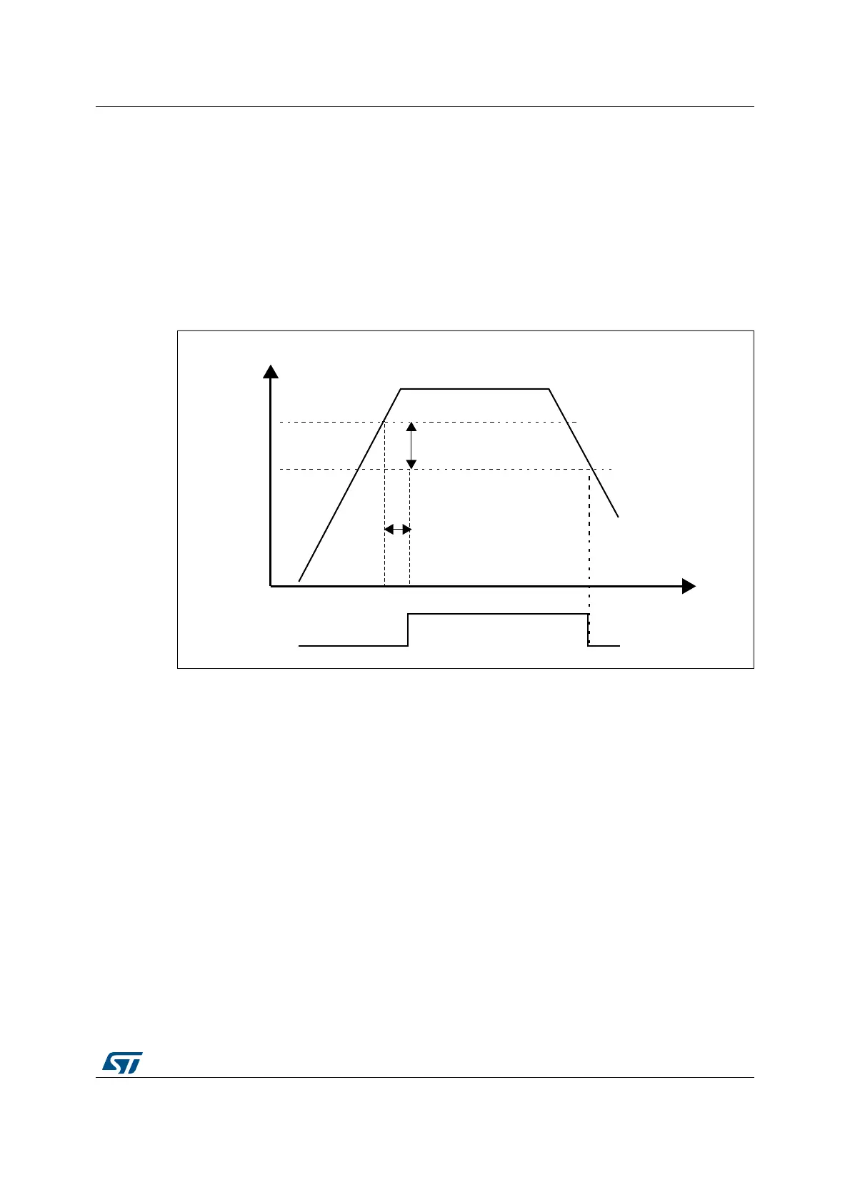
The devices have an integrated POR/PDR circuitry that allows a proper operation starting
from 1.71
V.
The devices remain in reset mode when V
DD
is below a specified threshold, VPOR/PDR,
without the need for an external reset circuit. For more details concerning the power
on/power-down reset threshold, refer to the electrical characteristics of the datasheet.
Figure 5. Power on reset/power down reset waveform
1. t
RSTTEMPO
is approximately 2.6 ms. VPOR/PDR rising edge is 1.66 V (typical) and VPOR/PDR falling edge
is 1.62 V (typical). Refer to the device datasheets for the actual values.
On the packages embedding the PDR_ON pin, the power supply supervisor is enabled by
holding PDR_ON high. On the other packages, the power supply supervisor is always
enabled.
1.3.2 Programmable voltage detector (PVD)
The PVD can be used to monitor the V
DD
power supply by comparing it to a threshold
selected by the PLS[2:0] bits in the PWR power control register (PWR_CR1).
The PVD is enabled by setting the PVDE bit.
A PVDO flag is available, in the PWR power control/status register (PWR_CSR1), to
indicate if V
DD
is higher or lower than the PVD threshold. This event is internally connected
to the EXTI line16 and can generate an interrupt if enabled through the EXTI registers.
The PVD output interrupt can be generated when V
DD
drops below the PVD threshold
and/or when V
DD
rises above the PVD threshold depending on EXTI line16 rising/falling
edge configuration. As an example the service routine could perform emergency shutdown
tasks.
9''9''$
P9
K\VWHUHVLV
3'5
3'5
069
5HVHW
7HPSRUL]DWLRQ
W5677(032
93253'5
ULVLQJHGJH
93253'5
IDOOLQJHGJH

 Loading...


