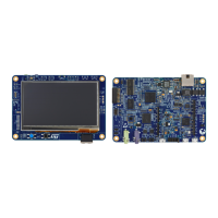
1. Set jumper JP8 in the E5V or CHGR position.
2. Connect the external power source to CN3 pin8 or CN15.
3. Check that the green LED LD4 is turned ON.
4. Connect the host PC to USB connector CN14.
Caution: If the board requests more than 300 mA and the host PC is connected via USB before the board is powered
from CN3 pin8 or CN15, the following events may occur (listed in reverse severity order):
1. The host PC is capable of supplying 300 mA (the enumeration succeeds) but does not feature any over-
current protection on its USB port. It is damaged due to over-current.
2. The host PC is capable of supplying 300 mA (the enumeration succeeds) and it has a built-in over-current
protection on its USB port, limiting or shutting down the power out of its USB port when the excessive
current demand from STM32H745I-DISCO/ STM32H750B-DK is detected. This causes an operating failure
of the board.
3. The host PC is not capable of supplying 300 mA (the enumeration fails). The STLINK-V3E does not supply
the rest of the STM32H745I-DISCO/STM32H750B-DK from its USB port VBUS line.
SMPS/LDO power supply
There are three solutions to provide power to the microcontroller V
CORE
logic supply: SMPS, LDO, and SMPS
and LDO. Power consumption in Run mode is significantly improved by generating V
CORE
from the internal
DC/DC converter (SMPS) and the default connection must be set to SMPS. Some modifications are required to
supply the microcontroller from the LDO. Below the board configuration for each case:
• LDO mode (default on the STM32H750XB): mount SB6, SB17 and SB45; remove SB5, SB18, SB26, SB27,
SB44, SB46 and L4.
• SMPS mode (default on the STM32H745XI): mount SB5, SB18, SB44, SB46 and L4; remove SB6, SB17,
SB27, SB26 and SB45.
• SMPS plus LDO mode: mount SB6, SB17, SB44, SB46 and L4; remove SB26, SB5, SB18, SB27 and SB45.
Using inconsistent firmware and hardware configurations for V
CORE
SMPS/LDO mode causes the board to be
bricked and unable to start up. To recover from this status, resolder the component according to the steps below:
1. Check the microcontroller firmware configuration regarding the V
CORE
power mode.
2. Resolder the solder bridge as described above for SMPS or LDO mode.
3. At power-on, check that the ST-LINK operates normally.
4. When the ST-LINK is connected, use the right SMPS/LDO configuration for your application.
Table 4. Power-supply related jumper and solder bridge settings describes the settings of all the jumpers related
to the powering of the STM32H745I-DISCO/STM32H750B-DK and the extension board. VDD_MCU corresponds
to the STM32H745XIH6/STM32H750XBH6 digital supply voltage line. It can be connected to a fixed 3.3 V supply.
UM2488
Power supply
UM2488 - Rev 4
page 12/55

 Loading...