6 Hardware layout and configuration
The STM32H745I-DISCO and STM32H750B-DK Discovery kits are designed around the STM32H745XIH6 and
STM32H750XBH6 microcontrollers, respectively. Both microcontrollers are packaged in TFBGA240+25. The
hardware block diagram (see Figure 3) illustrates the connection between the microcontroller and the peripherals
(SDRAM, eMMC, Quad-SPI Flash memory, FDCAN, LCD RGB connector, USB OTG connectors, UART,
Ethernet, Audio, TAG connector, STDC connector, ARDUINO
®
Uno shields and embedded ST-LINK). Figure 4
and Figure 5 help to locate these features on the STM32H745I-DISCO and STM32H750B-DK boards.
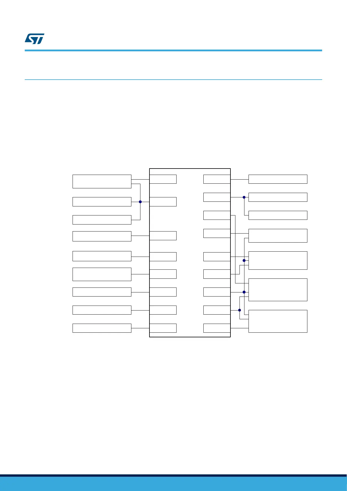
Figure 3. Hardware block diagram
STM32H745XI/STM32H750XB
in TFGA240+25
RTC
UART3
FMC
OTG
FDCAN1/2
SDMMC1
QSPI
PWR
32.768 kHz crystal
STLINK-V3E
128 Mbit SDRAM
USB connector
2x FDCANs
4 Gbyte eMMC
2x512 Mbit Quad-SPI Flash
memory
Power supply
STMod+ connector
ARD connector
MII
I2C4
TAG connector SWD
STDC connector
Ethernet
LCD
4.3 inch RGB LCD
SAI2
Audio Codec
PDM
SPI2
POE
UART2
UART1
UM2488
Hardware layout and configuration
UM2488 - Rev 4
page 7/55

 Loading...


