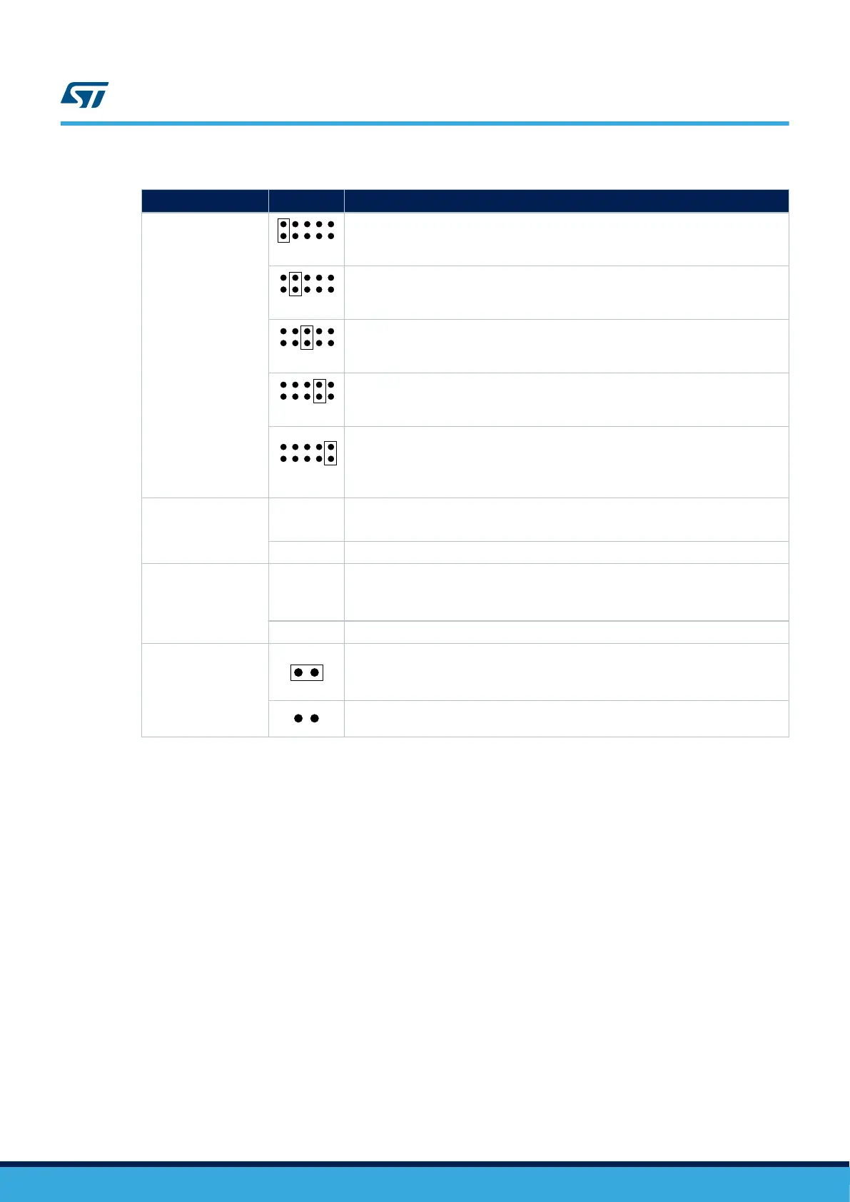
Table 4. Power-supply related jumper and solder bridge settings
Jumper/Solder bridge Setting Configuration
JP8
Power source selector
CHGR
ESV
POE5V
USBFS
STLK
The STM32H745I-DISCO/STM32H750B-DK is supplied through the CN14 Micro-B
USB receptacle.
CHGR
ESV
POE5V
USBFS
STLK
The STM32H745I-DISCO/STM32H750B-DK is supplied through the pin 8 of CN3
(marked VIN).
CHGR
ESV
POE5V
USBFS
STLK
The STM32H745I-DISCO/STM32H750B-DK is supplied through the RJ45 connector
CN1.
CHGR
ESV
POE5V
USBFS
STLK
The STM32H745I-DISCO/STM32H750B-DK is supplied through the CN13 Micro-AB
USB receptacle.
CHGR
ESV
POE5V
USBFS
STLK
Default setting
The STM32H745I-DISCO/STM32H750B-DK is supplied through the CN14 Micro-B
USB receptacle. It depends on host PC USB port powering capability declared in the
enumeration.
SB23
VBAT connection
SB23 ON
Default setting
VBAT is connected to +3V3.
SB23 OFF VBAT is not connected to +3V3.
SB15
VDD_USB connection
SB15 ON
Default setting.
VDD_USB (VDDUSB terminal of STM32H745XIH6/STM32H750XBH6) is connected
to VDD_MCU.
SB15 OFF VDD_USB is not connected to VDD_MCU.
JP1
VDD_MCU connection
Default setting
VDD_MCU (VDD terminals of STM32H745XIH6/STM32H750XBH6) is connected to
fixed +3.3 V.
VDD_MCU (VDD terminals of STM32H745XIH6/STM32H750XBH6) is not connected
to fixed +3.3 V
Note: STM32H750B-DK only supports the LDO mode.
6.5
Clock sources
Three clock sources are available on the STM32H745I-DISCO and STM32H750B-DK boards:
• X1: 25 MHz oscillator for STM32H745XIH6/STM32H750XBH6 microcontroller and Ethernet PHY.
• X2: 32 KHz crystal for STM32H745XIH6/STM32H750XBH6 embedded RTC
• X3: 25 MHz oscillator for STLK.
6.6 Reset sources
The reset signal of the STM32H745I-DISCO and STM32H750B-DK Discovery kits is active low. The reset
sources include:
• B2 reset button
• ARDUINO
®
Uno shield board from CN3
• Embedded STLINK-V3E
• TAG connector
• STDC14 receiver
• eMMC
UM2488
Clock sources
UM2488 - Rev 4
page 13/55

 Loading...


