7.5 CN2 STMod+ connector
An STMod+ connector is available on the STM32H745I-DISCO and STM32H750B-DK Discovery kits. It provides
flexibility in small form factor applications. In addition, the STMod+ connector expands the SPI interface and frees
I/Os that can be used by other peripheral expansions.
Table 10. CN2 STMod+ connector
Pin number Description Pin number Description
1 SS/CTS (PA15/PA0) 11 INT (PH12)
2 MOSI/TXD (PB15/PD5) 12 RESET (PH10)
3 MISO/RXD (PI2/PD6) 13 ADC (PA4)
4 SCK/RTS (PD3/PD4) 14 PWM (PA3)
5 GND 15 5V
6 5V 16 GND
7 I2C_SCL (PD12) 17 GPIO (PH1)
8 MOSIs (PI3) 18 GPIO (PI11)
9 MISOs (PB14) 19 GPIO(PH4)
10 I2C_SDA (PD13) 20 GPIO(PH8)
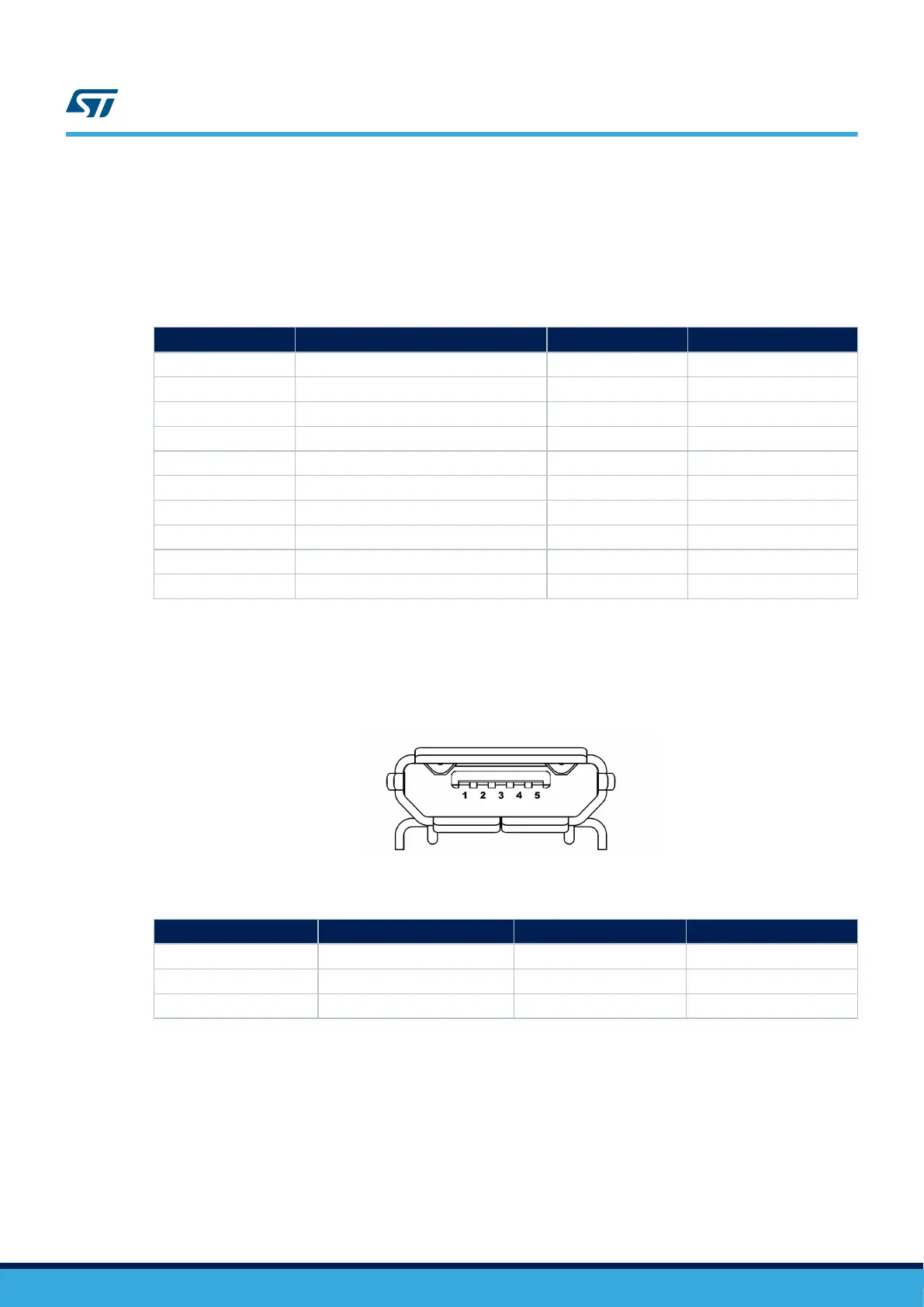
7.6 CN14 STLINK-V3 USB Micro-B connector
The CN14 USB connector is used to connect the embedded STLINK-V3E to the host PC in order to program and
debug the STM32H745XIH6/STM32H750XBH6 microcontroller.
Figure 10. CN14 USB Micro-B connector (front view)
Table 11. CN14 USB Type-B connector
Pinnumber Description Pin number Description
1 VBUS (power) 4 GND
2 DM 5, 6 Shield
3 DP - -
7.7 Audio stereo speaker header connectors (CN17 and CN18)
The stereo audio outputs, CN17 and CN18, can support the left and right stereo speakers, respectively.
7.8 CN9 audio line output (green jack) connector
A 3.5 mm stereo audio green jack output, CN9, can support the headphone.
UM2488
CN2 STMod+ connector
UM2488 - Rev 4
page 19/55

 Loading...


