Power supplies AN4938
16/46 AN4938 Rev 4
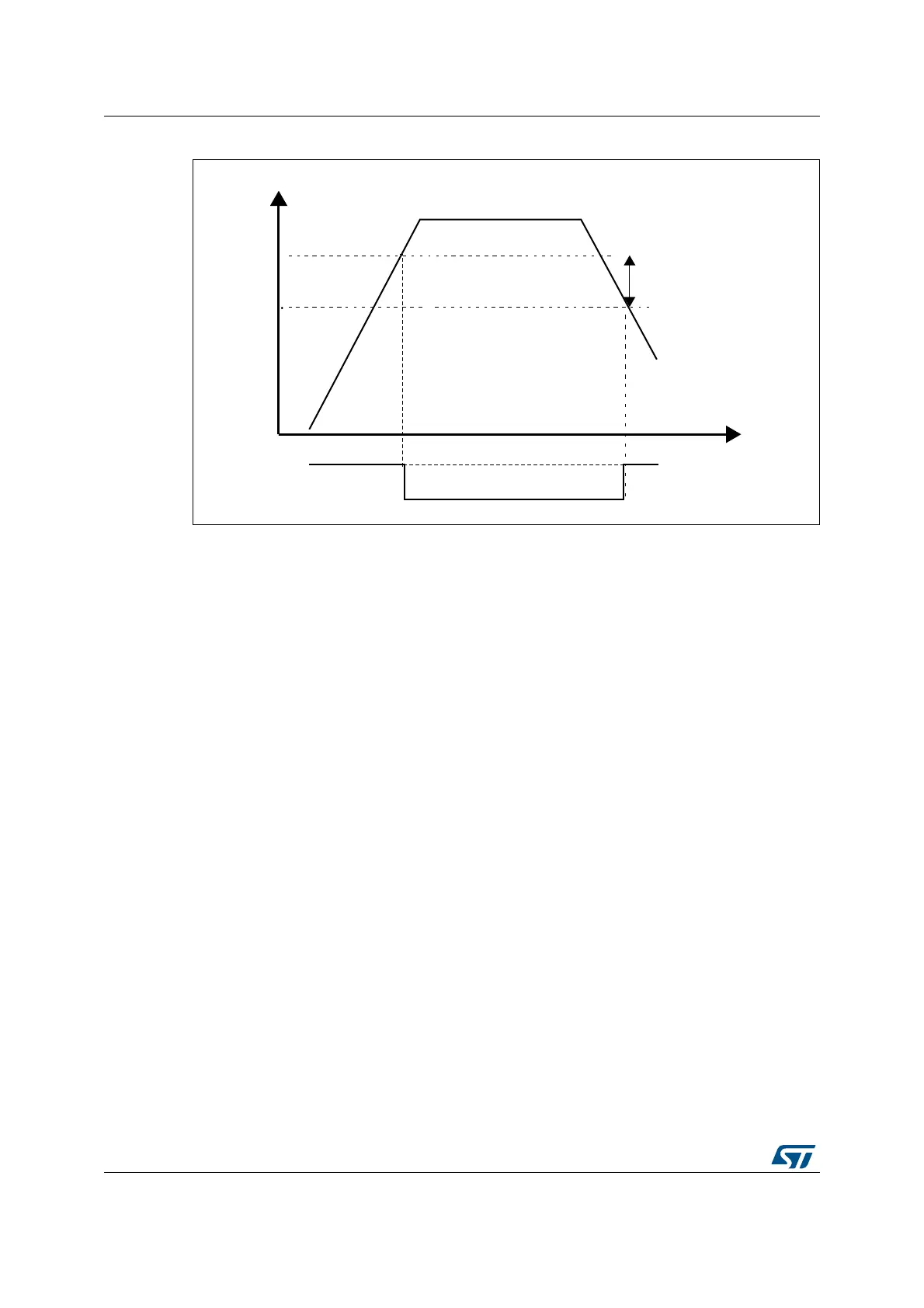
Figure 5. PVD threshold
2.3.3 Analog voltage detector (AVD)
The AVD can be used to monitor V
DDA
power supply by comparing it to a threshold selected
through the ALS[1:0] bits of the PWR power control register (PWR_CR1). The threshold
value can be configured to 1.7, 2.1, 2.5 or 2.8 V (refer to the devices datasheets for the
ac
tual values).
The AVD is enabled by setting the AVDEN bit in PWR_CR1 r
egister. An interrupt can be
raised when V
DDA
goes above or below the configured threshold.
2.3.4 System reset
A system reset sets all the registers to their default values except the reset flags in the clock
controller RCC_RSR register and the registers in the backup domain (see Figure 6).
A system reset (n
reset signal) resets all registers to their default values except for the reset
flags in the clock controller RCC_RSR (or RCC_C1_RSR) register and the registers in the
backup domain.
A system reset can be generated when one of the following events occurs:
• A low level on the NRST pin (external reset)
• A reset from the brownout reset block via the pwr_bor_r
st internal signal
• The input voltage (V
DD
) drops below a threshold level (pwr_por_rst)
• The independent watchdog end-
of-count condition (iwdg1_out_rst)
• A window watchdog end -of-count condition (wwdg1
_out_rst)
• A reset from low-power mode (lp
wr_rst)
• A software reset from the Arm
®
Cortex
®
-M7 core, generated via the SFTRESET signal.
069
9''
P9
K\VWHUHVLV
39'WKUHVKROG
39'RXWSXW
939'
ULVLQJHGJH
939'
IDOOLQJHGJH
 Loading...


