Jumper Description
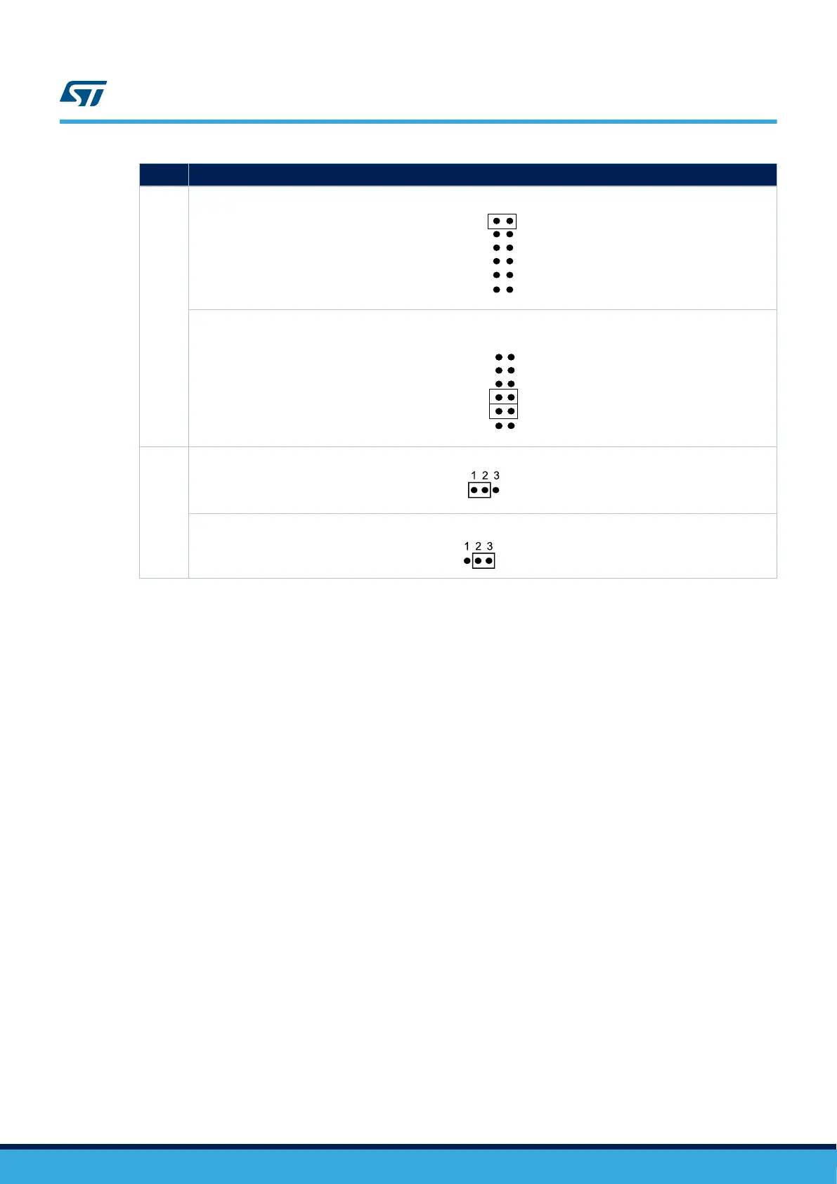
JP10
To supply the STM32H7x7I-EVAL board through the USB OTG1_HS (CN14), set JP10 as shown below:
HS
FS1
FS2
D5V
PSU
STlk
To supply the STM32H7x7I-EVAL board and the daughterboard connected on CN6 and CN7 through the power
supply jack (CN10), set JP10 as shown below (daughterboard must not have its power supply connected)
HS
FS1
FS2
D5V
PSU
STlk
JP11
V
BAT
is connected to +3.3 V when JP11 is set as shown below: (Default setting)
V
BAT
is connected to the battery when JP11 is set as shown below:
The LED LD9 lights up when the STM32H7x7I-EVAL Evaluation board is powered by the 5 V correctly.
Note: To avoid the impact of USB PHY, Ethernet PHY and get precise results about current consumption on JP9, take
into account the following cautions:
1. Remove JP5 to avoid Ethernet PHY influence.
2. Configure USB HS PHY into low-power mode (Register Address=04, bit 6 in USB PHY)
UM2525
Power supply
UM2525 - Rev 3
page 13/69