Connectors UM1018
20/44 Doc ID 18141 Rev 1
3.3 Power connector (CN12)
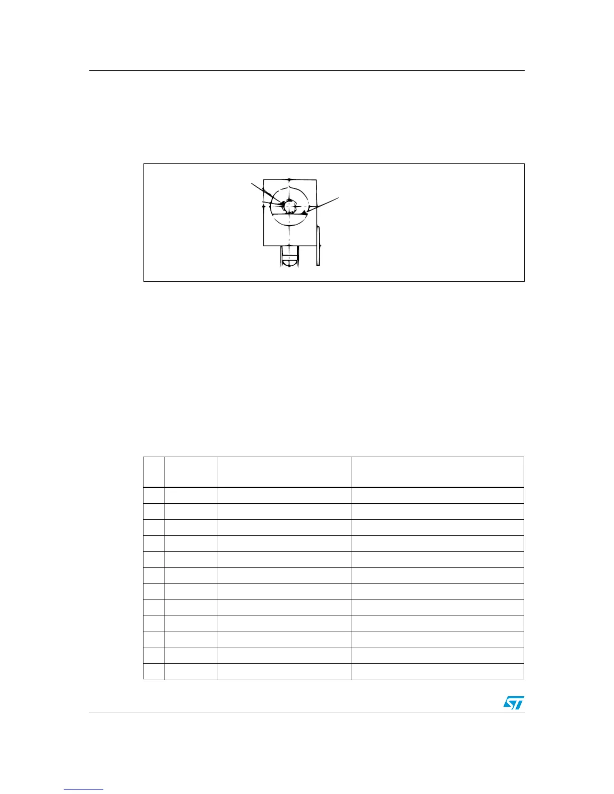
Your STM32L152-EVAL evaluation board can be powered from a DC 5 V power supply via
the external power supply jack (CN12) shown in Figure 7. The central pin of CN12 must be
positive.
Figure 7. Power supply connector CN12 (viewed from front)
3.4 Daughterboard extension connectors (CN6 and CN7)
Two 50-pin male headers CN6 and CN7 can connect a daughterboard or standard wrapping
board to the STM32L152-EVAL evaluation board. All GPIOs are available on it. The space
between these two connectors and position of power, GND and RESET pins are defined as
a standard which allows common daughterboards to be developed for several evaluation
boards. The standard width between CN6 pin1 and CN7 pin1 is 2700 mils (68.58 mm). This
standard is implemented on the majority of evaluation boards.
Each pin on CN6 and CN7 can be used by a daughterboard after disconnecting it from the
corresponding function block on the STM32L152-EVAL evaluation board. Please refer to
Tabl e 1 5 and Ta b l e 16 for details.
Table 15. Daughterboard extension connector CN6
Pin Description Alternative function
How to disconnect with function block on
STM32L152-EVAL board
1GND - -
3 PC7 TS_KEY2 Remove R13
5 PC9 TS_CT Remove R29
7 PA9 COM1 Remove LCD glass U20
9PA0 Tamper/Key -
11 PC14 32K OSC Remove R37
13 PA12 USB DP Remove R25
15 PC15 32K OSC Remove R38
17 PC10 LCD glass_SEG40 / USART3_TX JP7 open
19 GND - -
21 PC12 LCD glass_SEG42 Remove LCD glass U20
23 PD1 LED2 Remove R125