Hardware and layout UM1018
10/44 Doc ID 18141 Rev 1
2.5 Boot option
The STM32L152-EVAL evaluation board is able to boot from:
● Embedded user Flash
● System memory with boot loader for ISP
● Embedded SRAM for debugging
The boot option is configured by setting switch SW1 (BOOT0) and SW2 (BOOT1). The
BOOT0 can also be configured via RS-232 connector CN2.
2.6 LCD glass module
An LCD glass module, U20, with 8-digit liquid crystal display is mounted on the
STM32L152-EVAL evaluation board. It is connected to the LCD controller of
STM32L152VBT6.
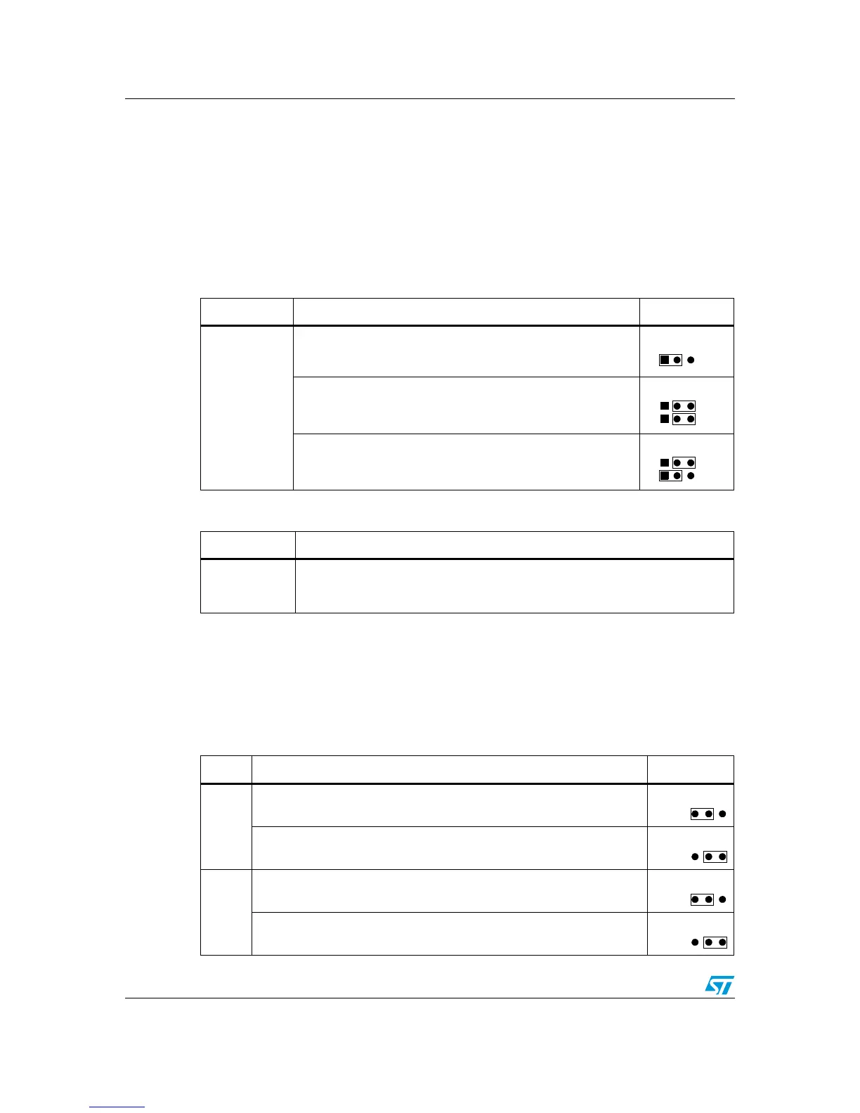
Table 4. Boot related switches
Switch Boot from Setting
SW1 and SW2
STM32L152-EVAL boot from embedded user Flash when SW1
is set as shown. SW2 is not relevant in this configuration (default
setting).
STM32L152-EVAL boot from embedded SRAM when SW1 and
SW2 are set as shown.
STM32L152-EVAL boot from system memory when SW1 and
SW2 are set as shown.
Table 5. Boot0 related jumper JP6
Jumper Description
JP6
Bootloader_BOOT0 is managed by pin 6 of CN2 (RS-232 DSR signal) when JP6
is closed. This configuration is used for boot loader application only.
Default setting: Not fitted.
Table 6. LCD glass related jumpers
Jumper Description Setting
JP7
PC10 is connected to LCD glass as SEG40 when JP7 is set as shown
(default setting).
PC10 is connected to USART3_TX when JP7 is set as shown.
JP8
PC11 is connected to LCD glass as SEG41 when JP8 is set as shown
(default setting).
PC11 is connected to USART3_RX when JP8 is set as shown.