UM1018 Connectors
Doc ID 18141 Rev 1 19/44
3 Connectors
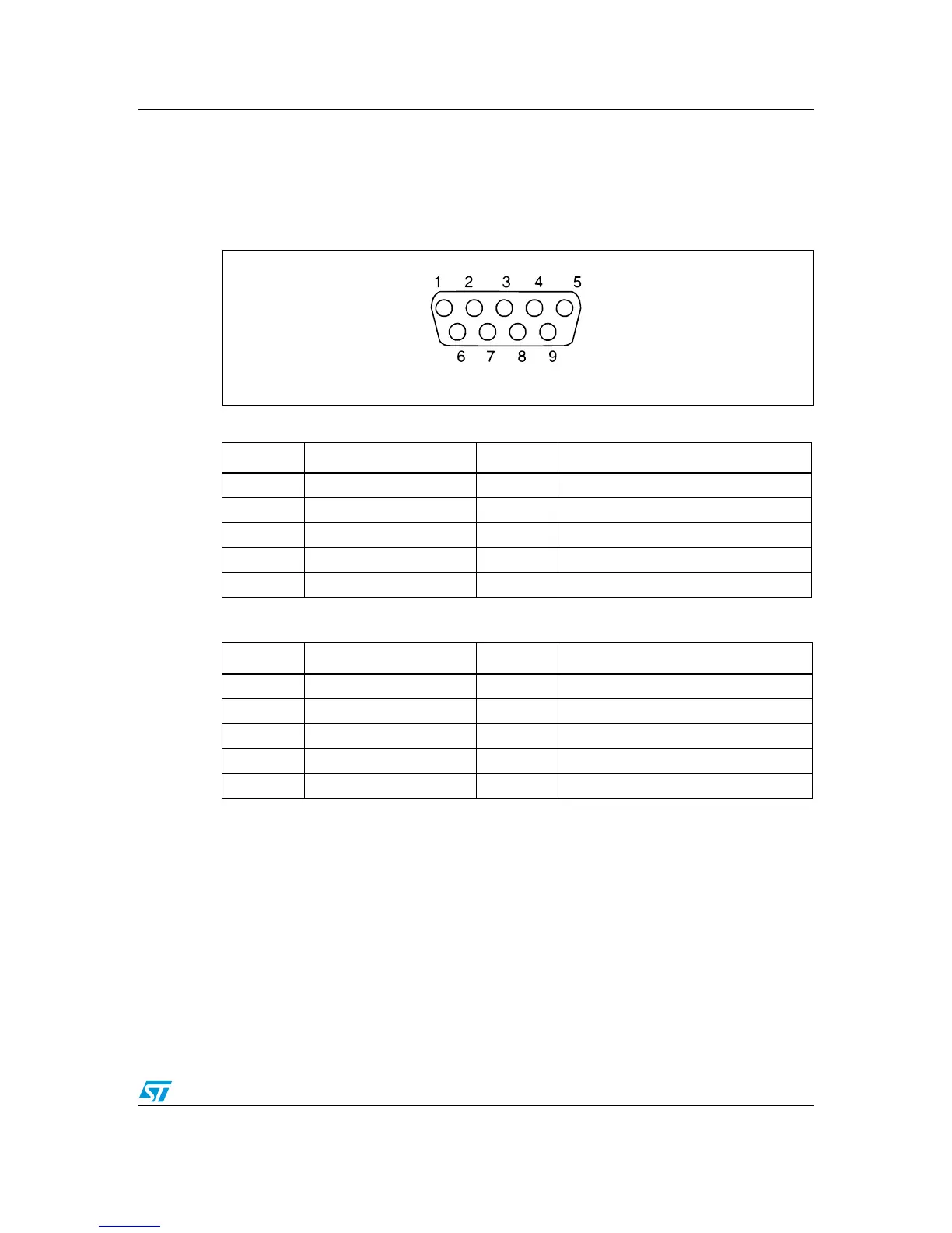
3.1 RS-232 connectors (CN2, CN5)
Figure 6. RS-232 connector (viewed from front)
3.2 TFT LCD connector (CN14)
A TFT color LCD board (MB895) is mounted on CN14.
Table 13. RS-232 connector CN2 with HW flow control and ISP support
Pin number Description Pin number Description
1 6 Bootloader_BOOT0
2 RS-232_RX (PD6) 7 RS-232_RTS(PD4)
3 RS-232_TX (PD5) 8 RS-232_CTS(PD3)/Bootloader_RESET
4NC 9NC
5GND
Table 14. RS-232 connector CN5
Pin number Description Pin number Description
1 NC 6 Connected to pin4
2 RS-232_RX (PC11) 7 Connected to pin8
3 RS-232_TX (PC10) 8 Connected to pin7
4 Connected to pin6 9 NC
5GND