7.2.3 5 V power supply
The STM32WB5MM-DK Discovery kit can be powered by a 5 V DC power source. The 5V signal can come from
several connectors:
• 5V_USB_STLK connected to CN11 (default configuration for the supply of the board). This connector is
dedicated to access to the STLINK/V2 and Virtual COM port and can supply power from the host computer.
It is also possible to connect a USB charger to this connector. In this case, the ST-LINK and the Virtual COM
port cannot be accessible.
• 5V_USB_MCU connected to User USB. This USB port is directly connected to the STM32W5MMG as a
USB port. The same remark applies as for 5V_USB-STLK, the supply can be provided by the host computer
or by USB charger.
• Ext input (CN8). Be careful, in this case, the state of the jumpers and the solder bridges is very important.
Refer to Section 7.2.2 for details.
• 7-12V input through the U9 voltage regulator. Refer to Section 7.2.2 for details.
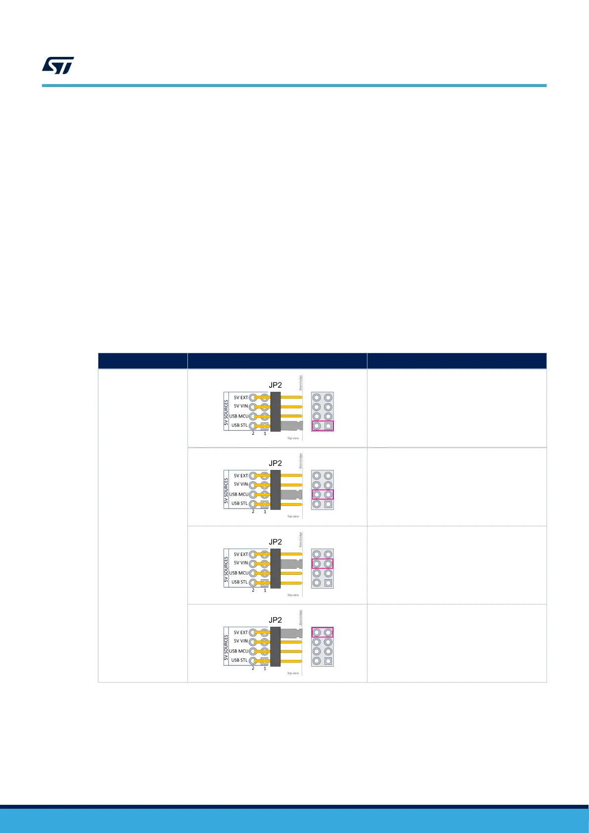
The JP2 jumper JP2 selects the 5V source. Table 4 shows the configuration for the selected source.
Caution: Depending on the current needed on the devices connected to the USB port, and the board itself, power
limitations can prevent the system from working as expected. The user must ensure that the STM32WB5MM-DK
Discovery kit is supplied with an adequate power source depending on the needed current.
Table 4. JP2 power supply selector description
Jumper/solder bridge
Setting
Configuration
(1)
JP2
5V supply
source selector
STM32WB5MM-DK is supplied through the
CN11 Micro-B USB receptacle (USB_STLINK).
STM32WB5MM-DK is supplied through CN6
Micro-B receptacle (USB_USER).
STM32WB5MM-DK is supplied through pin 8
of CN2 (ARDUINO
®
) or CN8 (Refer to the
configuration details on the present power supply
section).
STM32WB5MM-DK is supplied through CN8
directly (Refer to the configuration details on the
present power supply section).
1. The default configuration is in bold
When 5V_USB_STLINK is used and JP2 [1-2] ON, the sequence is specific. In the beginning, only STM32F103 is
supplied. If the USB enumeration succeeds, the 5V_USB_STLINK power is enabled by asserting the PWR_ENn
signal from STM32F103CBT6. This pin is connected to an STMPS2141STR power switch which supplies the rest
of the board. This power switch also features a current limitation to protect the PC in case of currents exceeding
300 mA.
UM2825
Power supply
UM2825 - Rev 1
page 13/42

 Loading...

