7.5.5 LEDs
Description
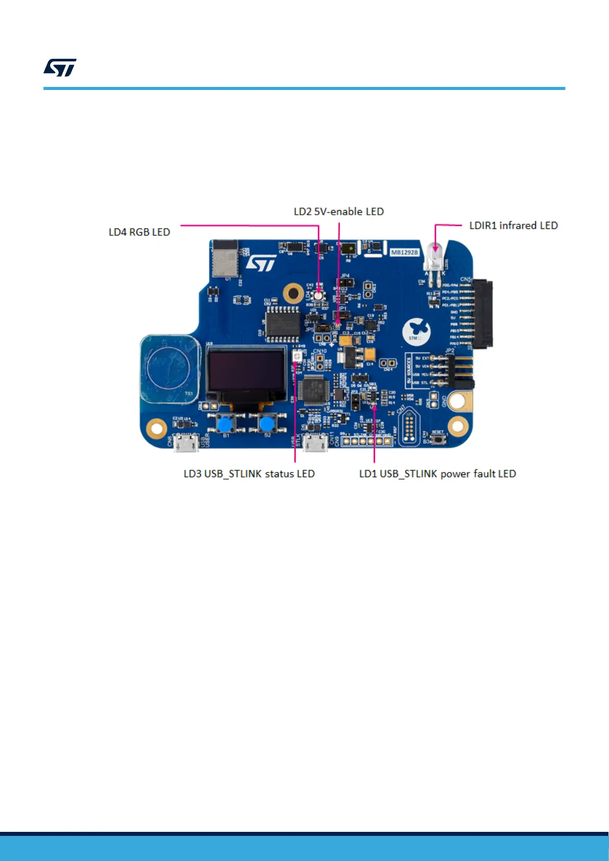
Five LEDs on the top side of the STM32WB5MM-DK board help the user during the application development.
Figure 10. LEDs location
• LD1: this red LED indicates that the current distribution could not be performed as expected.
• LD2: this LED turns green when the 5 V is available. Refer to Section 7.2.3 to select the 5 V source.
• LD3 COM: LD3 is a bi-color LED, which default status is red, turns to green to indicate that communication is
in progress between the PC and the ST-LINK/V2-1, as follows:
– Slow blinking red/OFF: at power-on, before USB initialization
– Fast blinking red/OFF: after the first correct communication between PC and ST-LINK/V2-1
(enumeration)
– Red ON: when initialization between PC and ST-LINK/V2-1 is successfully finished
– Green ON: after successful target communication initialization
– Blinking red/green: during communication with the target
– Green ON: communication finished and OK
– Orange ON: communication failure
• LD4: this LED is an RGB LED. It is available for the user application.
• LDIR1: this LED allows to transmit infrared radiation signal.
RGB LED
The resources coming from STM32W5MMG are shared between the RGB and IR LEDs. It is not possible to use
them simultaneously. The selection is done by JP4 and JP5 jumpers.
To use the RGB LED, JP5 must be ON and JP4 OFF. In this configuration, GPIO_SELECT2 (PH1) is the chip
select for this RGB device on SPI1.
The RGB LED is driven by the TLC59731 PWM LED driver from Texas Instruments.
UM2825
Board functions
UM2825 - Rev 1
page 17/42

 Loading...

