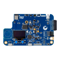
Infrared (IR) LED
The resources coming from STM32W5MMG are shared between the RGB and IR LEDs. It is not possible to use
them simultaneously. The selection is done by JP4 and JP5 jumpers.
To use the IR LED, JP4 must be ON and JP5 OFF. In this configuration, GPIO_SELECT2 (PH1) is the chip select
for this IR transmission. PB9 is in charge of the IR modulation. This GPIO is shared with the Quad-SPI Flash
Memory. It is possible to use the Flash Memory and IR LED on the same application but not exactly at the same
time.
The IR LED is driven by TIM16 and TIM17 internal timers. The schematic proposal does not use the IR_OUT
feature. A firmware example is available on the firmware package.
7.5.6 Push-buttons
Description
The STM32WB5MM-DK Discovery kit provides three buttons:
• B1 user push‑button
• B2 user push‑button
• B3 reset push‑button, used to reset STM32WB5MM-DK Discovery kit.
Reset push‑button
B3 is a small push‑button dedicated to the hardware reset of the STM32WB5MM-DK. It is separated from the
other push‑buttons to avoid mishandling.
User push‑buttons
There are two push‑buttons available for the user application. They are connected to PC12 and PC13. It is
possible to use them for GPIO reading or to wake up the device.
Table 8. Physical user interface I/O configuration (push‑buttons)
Name I/O Available wake-up
B1 user1 push‑button PC12 WKUP3
B2 user2 push‑button PC13 WKUP2
7.5.7 Touch sensor
The STM32WB5MM-DK board embeds a touch sensor. The touch sensor is working with the charge and
discharge of a capacitor. Touching the round panel with a finger charges a capacitor. Once the capacitor is
charged at VDD, the charge is transferred to another capacitor, called the sampling capacitor.
Two groups of I/Os are connected to use it:
Table 9. Physical user interface I/O configuration (touch sensor)
I/O group I/O Configuration
Shield group 4
PC6 TSC_G4_IO1
PC7 TSC_G4_IO2
Touch key group 6
PD10 TSC_G6_IO1
PD11 TSC_G6_IO2
UM2825
Board functions
UM2825 - Rev 1
page 18/42

 Loading...