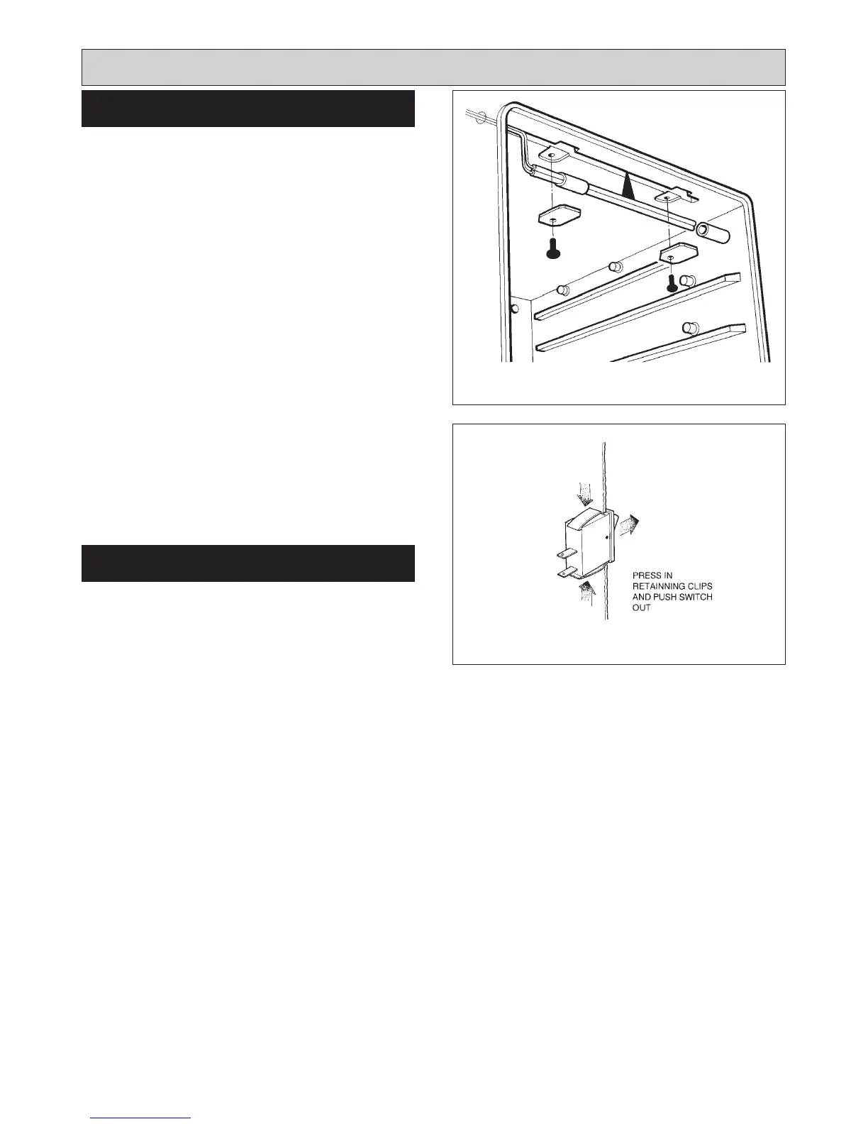
SEE FIG. 39
Follow instructions in section ELECTRICAL
COMPONENT ACCESS, Steps 1 to 6.
1. Undo the two screws on the front of the chassis which
holds the thermostat in place.
2. Remove the two push on connectors from back of
thermostat.
3. Open roasting oven door to access thermostat phial
and capillary which will pass into the oven at the top.
4. Where the phial passes through the roasting oven
side, slacken screw front phial, mounting bracket and
rotate.
5. Replace thermostat. The thermostat should be
mounted with tag P at the right hand side. Reposition
the phial in same position as removed.
6. Re-connect push on connector. The VIOLET to P2,
PINK to P and BLACK to P1.
NOTE: Ensure phials do not make contact with oven
castings.
To complete follow instructions in RE-ASSEMBLE, Steps
1 to 6.
SEE FIG. 40
Follow instructions in section ELECTRICAL
COMPONENT ACCESS, Steps 1 to 4.
1. To remove switch from the cover panel press the two
toggles at top and bottom of switch, push switch
through panel.
2. Push replacement switch into aperture and click into
place. The switch should be fitted with terminal 1 at the
top.
To complete follow the instructions in section RE-
ASSEMBLE, Steps 3 to 6.
Replacement of parts
(Electrical controls)
22
TO FIT NEW SELECTOR SWITCH
FIG. 39 DESN 514831
TO FIT NEW OVEN CONTROL
THERMOSTAT
FIG. 40 DESN 510553 A