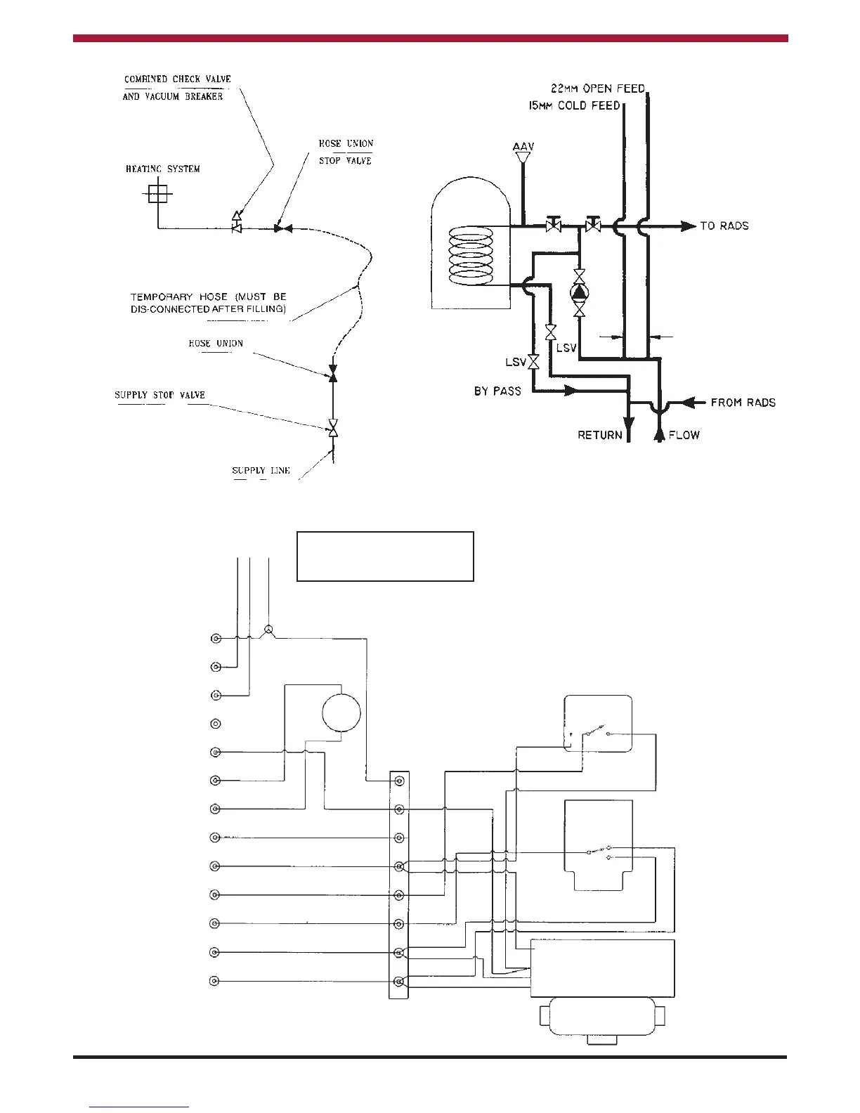
PROVISION FOR FILLING SEALED SYSTEM
Fig.23
19
S PLAN SYSTEM
Fig.24
COLD FEED
PIPE & OPEN
VENT PIPE
NOT MORE THAN
150mm (6”) APART
EARTH
MAINS
EARTH POST
NEUTRAL
LIVE
FLUE FAN
INTERSTAT
PUMP L
PUMP N
NEUTRAL
GREEN/YELL
WHITE
BLUE
GREY
HONEYWELL
V4073A
L641A
Cyl.Stat
T6360B
Room Stat
ORANGE
HEATING Timer
DHW Timer
NO DHW Timer
Boiler Run
Brandon
TERMINALS
WIRING
CENTRE
PERMANENT
(FUSED) LIVE
PUMP
C
2
3
1
2
Y - PLAN WIRING DIAGRAM Fig.25
Note:
It is essential that the interstat can bring on the
motorised valves directly as shown, failure to observe
this will result in nuisance lockout.
Please Note:
EARTHS NOT SHOWN FOR CLARITY
CONNECT EARTHS IN ACCORDANCE
WITH REGULATIONS!
If wires are a different colour
code, please refer to the
manufacturers instructions.
1
2
4
5
6
7
8
9
10
1
1
12
13
3
 Loading...