21
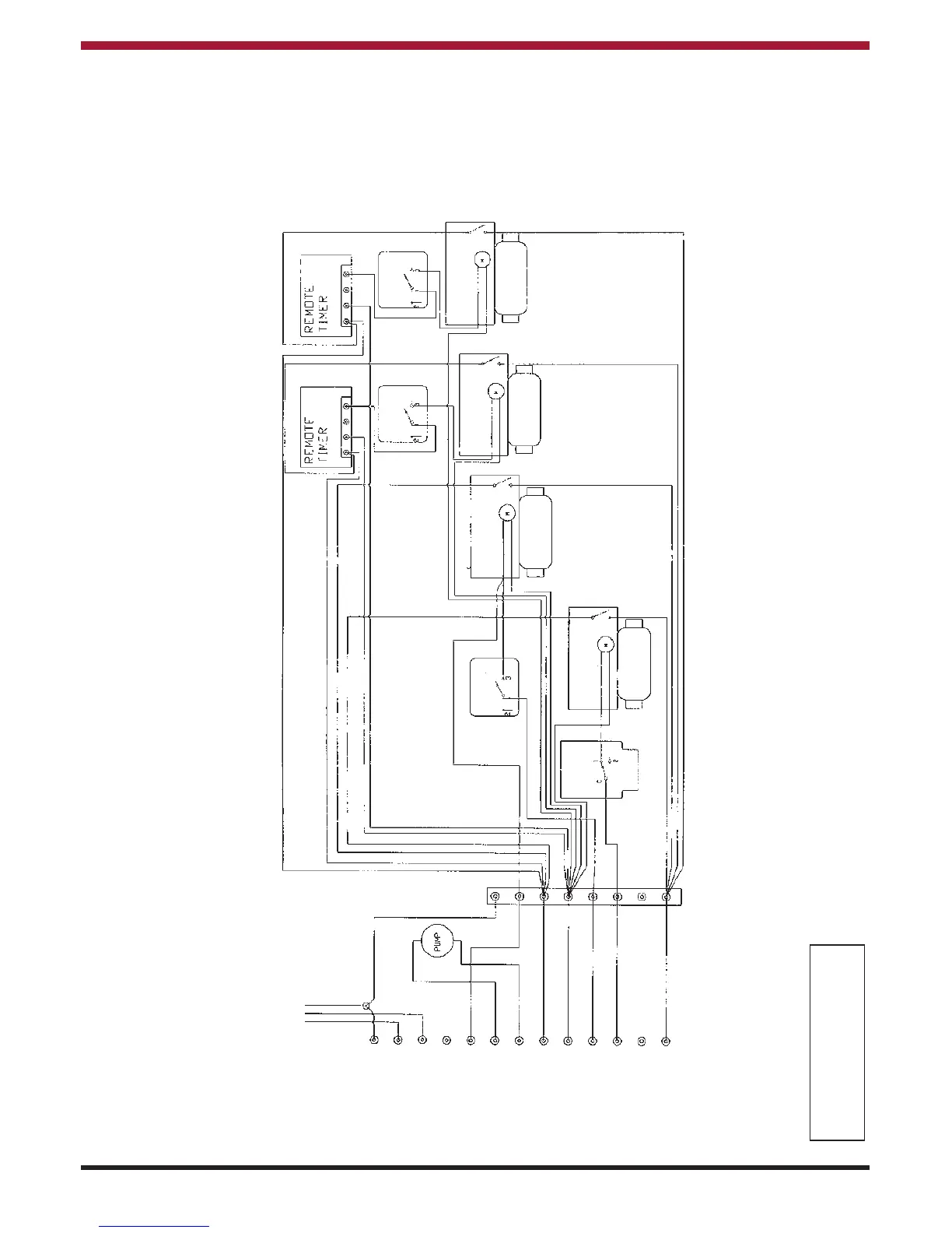
S PLAN WIRING DIAGRAM USING MULTI TIMER FOR ALL CENTRAL HEATING ZONES Fig. 27
EARTH
MAINS
EARTH POST
NEUTRAL
LIVE
FLUE FAN
INTERSTAT
PUMP L
PUMP N
NEUTRAL
HEATING Timer
DHW Timer
NO DHW Timer
Boiler Run
Brandon
TERMINALS
WIRING
CENTRE
PERMANENT
(FUSED) LIVE
BROWN
BROWN
GREY
GREY
GREY
GREY
BLUE
BLUE
GREY
BLUE
BROWN
BROWN
ORANGE
Note:
It is essential that the interstat can bring on one of the motorised valves
directly as shown, failure to observe this will result in nuisance lockout.
Please Note:
EARTHS NOT SHOWN FOR CLARITY
CONNECT EARTHS IN ACCORDANCE
WITH REGULATIONS!
BROWN
T6360B
Room Stat
T6360B
Room Stat
T6360B
Room Stat
L641A
Cyl. Stat
Motorised Valve
Domestic Hot Water
Motorised Valve
Wet Heating ZONE 1
Motorised Valve
Wet Heating ZONE 2
Motorised Valve
Wet Heating ZONE 3
If wires are a different colour
code, please refer to the
manufacturers instructions.
1
2
4
5
6
7
8
9
10
1
1
12
13
3
 Loading...