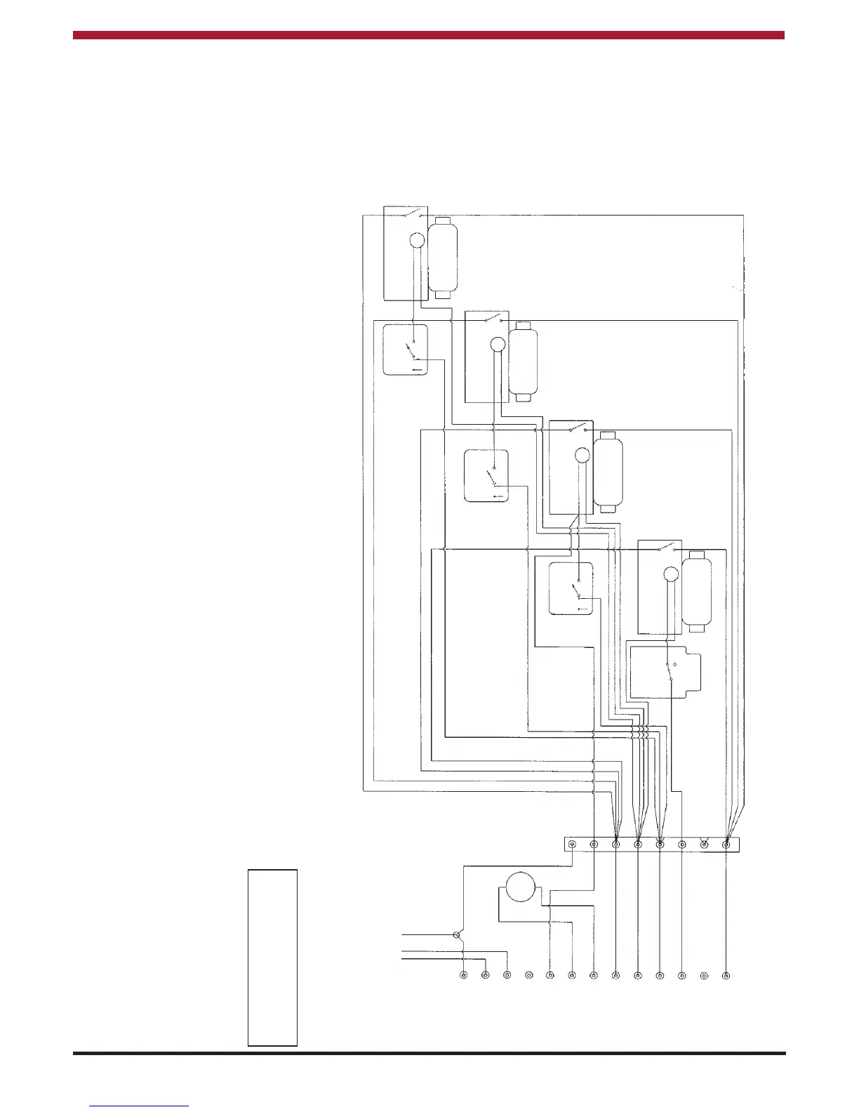
4 ZONE HEATING SYSTEM
When connecting the a Brandon cooker to a 4 -
zoned heating system (i.e. separate time switches
and thermostats for domestic hot water and four
central heating zones), the domestic hot water and
one zone must be controlled directly from the
cooker enabling the inter thermostat to
operate if necessary. All other zones can
be controlled from the cooker where a
constant live supply must be connected to
the time clocks only (see figure 27).
Under no circumstances can other supply
sources be connected directly to the cooker.
4 ZONE HEATING SYSTEM
22
EARTH
EARTH POST
MAINS
NEUTRAL
LIVE
FLUE FAN
INTERSTAT
PUMP L
PUMP N
NEUTRAL
HEATING Timer
DHW Timer
NO DHW Timer
Boiler Run
Brandon
TERMINALS
WIRING
CENTRE
PERMANENT
(FUSED) LIVE
PUMP
If wires are a different colour
code, please refer to the
manufacturers instructions.
L641A
Cyl.Stat
T6360B
Room Stat
T6360B
Room Stat
T6360B
Room Stat
Motorised Valve
Domestic Hot Water
Motorised Valve
WET HEATING ZONE 1
Motorised Valve
WET HEATING ZONE 2
Motorised Valve
WET HEATING ZONE 3
c
1
2
3
2
3
2
2
3 -
M
M
M
M
Blue
Blue
Blue
Brown
Brown
Brown
Orange
Grey
Grey
Grey
Grey
Brown
S PLAN WIRING DIAGRAM USING SAME TIMER FOR ALL CENTRAL HEATING
ZONES Fig. 28
1
2
4
5
6
7
8
9
10
1
1
12
13
3
 Loading...