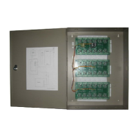
Dual Controller Option
It is possible to increase the number of keyholders by connecting a reader to the same door
channel on two Easikey 250 Controllers. If a key is found in either of the Controllers then
the lock relay will operate. The diagrams below show two controllers controlling one Lock 1.
To control Lock 2, connect a single reader to channel 2 of both controllers, and the lock
through terminals L3 and L4 of each controller. Note that power is supplied to both Easikey
250 controllers.
Note: You can connect two Easikey 250s, or connect an Easikey 250 and an Easikey 99. In
the diagrams below, Controller 1 is always an Easikey 250; Controller 2 may be
either an Easikey 250 or an Easikey 99. The connections for reader and lock wiring
are identical on an Easikey 99 and an Easikey 250.
Reader Wiring
Notice that the reader wiring shown below includes a diode (1N4001, not supplied) at each
A1 (or A2) terminal. This is essential to provide correct operation of the reader LED.
The Request to Exit switch can be fitted to either controller.
-V1 S1 R1 A1 +V1
+
Reader Wiring for Dual Controller Operation
1 Easikey 250 Controller, Door Channel 1 L Request to Exit
2 Easikey 99 / 250 Controller, Door Channel 1 Y Diodes, 1N4001
B Reader
41
 Loading...