ENGLISH (Original Instructions)
30
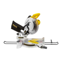
BLADES
WARNING! To minimize the risk of eye injury, always
use eye protection. Carbide is a hard but brittle material.
Foreign objects in the workpiece such as wire or nails
can cause tips to crack or break. Only operate saw when
proper saw blade guard is in place. Mount blade securely
in proper rotation before using, and always use clean,
sharp blade.
If you need assistance regarding blades, please contact
your local STANLEY dealer.
Depth of Cut Adjustment (FIG. E–G)
1. Raise the depth adjustment lever (16) to loosen.
2. To obtain the correct depth of cut, align the notch (17)
on the depth adjustment strap with the appropriate mark
on the upper blade guard (12).
3. Tighten the depth adjustment lever.
4. For the most efficient cutting action using a carbide
tipped saw blade, set the depth adjustment so that
about one half of a tooth projects below the surface of
the wood to be cut.
5. A method of checking for the correct cutting depth is
shown in (FIG. G). Lay a piece of the material you plan
to cut along the side of the blade, and observe how
much tooth projects beyond the material.
Bevel Angle Adjustment (FIG. H)
The bevel angle adjustment mechanism (7) can be adjusted
between 0° and 45°.
1. Turn the bevel adjustment knob (6) to loosen.
2. Tilt the foot plate to the desired angle mark on the pivot
bracket (21).
3. Turn the bevel adjustment knob to retighten.
Kerf Indicator (FIG. I)
The front of the saw shoe has a kerf indicator (20) for
vertical and bevel cutting. This indicator enables you to
guide the saw along cutting lines penciled on the material
being cut. The indicator lines up with the left (inner) side
of the saw blade, which makes the slot or “kerf” cut by the
moving blade fall to the right of the indicator. The notches
on the base plate indicate 0º and 45º.
Mounting and Adjusting the Parallel Fence (FIG. J)
The parallel fence (22) is used for cutting parallel to the
edge of the workpiece.
MOUNTING (FIG. J-K)
1. Insert parallel fence adjustment knob (23) into the hole
(25) as shown in (FIG. J), keeping the knob loose to
allow the parallel fence to pass.
2. Insert the parallel fence (22) into the base plate (8) as
shown in (FIG. J).
3. Tighten the parallel fence adjustment knob (23).
ADJUSTING
1. Slacken the fence adjustment knob (23) and set the
parallel fence (22) to the desired width. The adjustment
can be read on the parallel fence scale.
2. Tighten the fence adjustment knob (23).
Prior to Operation
♦ Make sure the guards have been mounted correctly.
The saw blade guard must be in closed position.
♦ Make sure the saw blade rotates in the direction of the
arrow on the blade.
♦ Do not use excessively worn saw blades.
AFTER USE
♦ After switching off the tool, never stop the rotation of the
accessory by a lateral force applied against it.
USE
WARNING! Always wear gloves when you change
accessories. The exposed metal parts on the tool and
accessory may become extremely hot during operation.
Please operate tool with normal load. Do not overload. Do
not abuse the tool, please refer instruction manual to use
the tool correctly.
Instructions for Use
WARNING! Always observe the safety instructions and
applicable regulations.
WARNING! To reduce the risk of injury, turn unit off
and disconnect machine from power source before
installing and removing accessories, before adjusting
or changing set-ups or when making repairs. An
accidental start-up can cause injury.
Proper Hand Position (FIG. K)
WARNING: To reduce the risk of serious personal injury,
always use proper hand position as shown.
WARNING: To reduce the risk of serious personal injury,
always hold securely in anticipation of a sudden reaction.
Proper hand position requires one hand on the main handle
(2), with the other hand on the auxiliary handle (5).
Switching On and Off (FIG. A)
To run the tool, press the ON/OFF-switch (1).
To stop the tool, release the ON/OFF-switch. Always
switch OFF the tool when work is finished and before
unplugging.
Switching On and Off (safety switch) (FIG. A)
If your saw is equipped with a safety switch to prevent
inadvertent operation, please follow the below instruction.
To run the tool, press the lock-off button (13) and
subsequently press the ON/OFF-switch (1). Release the
lock-off button (13).
To stop the tool, release the ON/OFF-switch (1). Always
switch OFF the tool when work is finished and before
unplugging.
Notice: Do not switch the tool ON or OFF when the saw
blade touches the workpiece or other materials.
Workpiece Support (FIG. L–P)
WARNING: To reduce the risk of serious personal
injury, support the work properly and hold the saw
firmly to prevent loss of control.
 Loading...