32 • ENGLISH
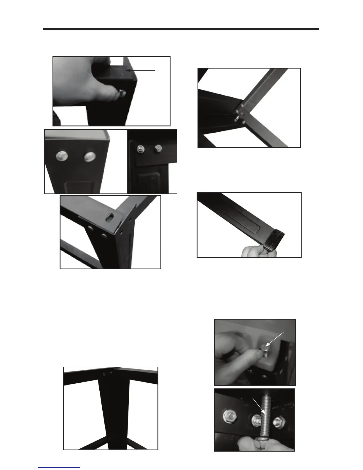
Step 2
Repeat Step 1 so that there are two frames assembled.
Step 3
Select the following parts:
2 x Part 2
2 x Part 4
These will form the crosspieces between the
previously assembled frames. Lay the parts flat on
the floor. Connect the longer Part (2) and fix it to the
frame in the center of the uprights. Note that Part
2 should be positioned as shown in Fig. B4. Connect
Part 4 (top cross support) to the top of the frame. Note
that Part 4 should be positioned as shown in Fig. B4.
Step 4
Now place and connect the ends of the top and center
frame supports to the frame. Take care to ensure that
the supports are positioned as shown in Fig. B5.
Step 5
Once you are satisfied that the frame is assembled
correctly, fully tighten ALL the bolts.
Finally, assemble the 4 foot pads to the bottom of
each leg (see Fig. B6).
Fitting the table saw to the stand (see FIG. C1, C2)
There are four mounting holes on the base of the saw.
4 corresponding mounting holes are located on the top
plane of the stand. Put the table saw on the stand, match
the holes on the base of the saw with the holes on the
stand, and secure them with the 4 bolts (b) provided. DO
fully fasten.
a
B1
B2
B3
5
3
1
2
B4
4
51
4
B5
B6
C1
b
b
C2