ENGLISH • 33
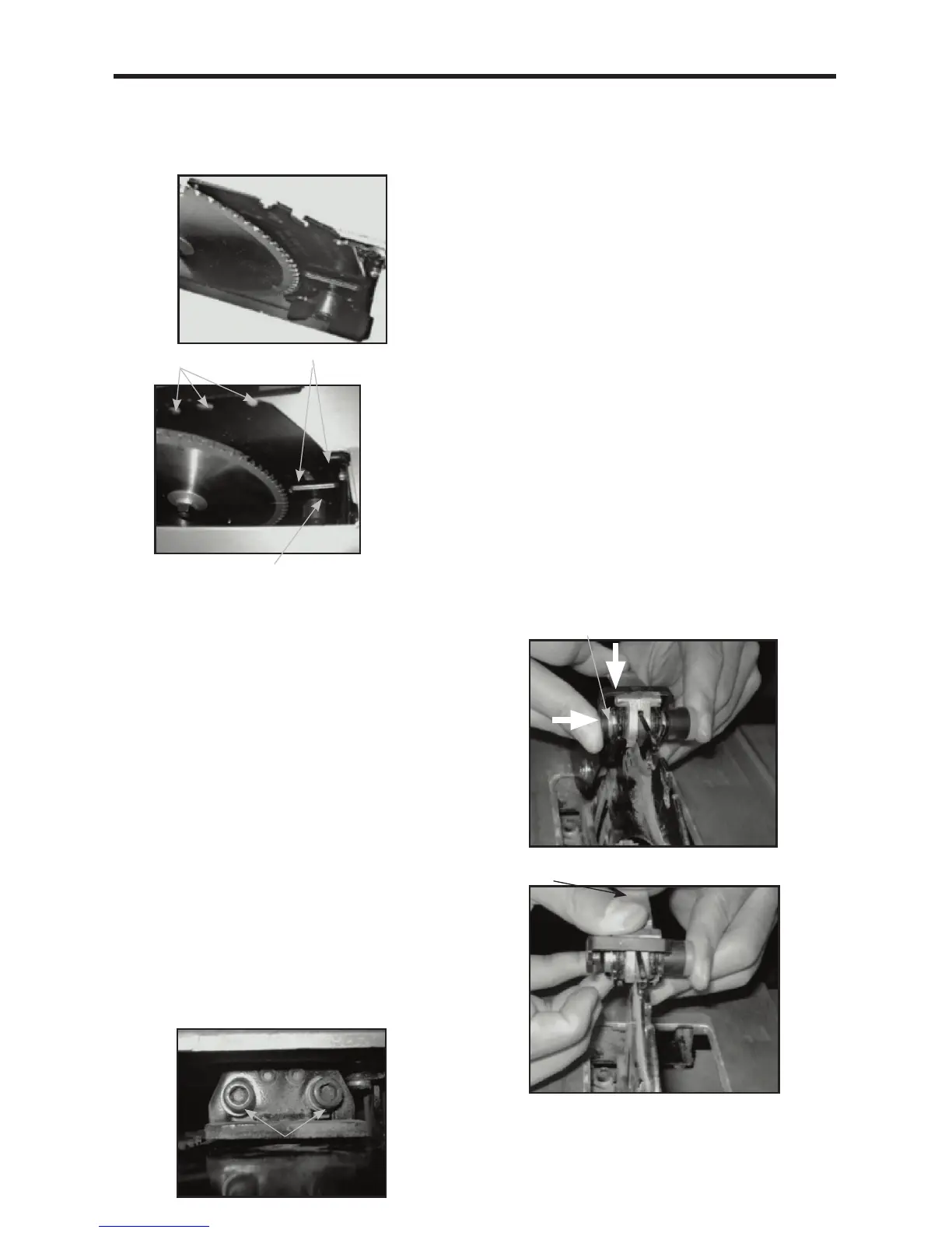
Adjusting the splitter (FIG. D1-D3)
The splitter (3) has two positions: storage position (Fig.
D1) and working position (Fig. D2). The splitter is in the
storage position when you take it out of the package.
To place the splitter in the working position:
a. Remove the blade throat plate.
b. Raise the blade up to the highest position by turning
the blade control wheel counterclockwise. Set the
bevel at 0°. Make sure the bevel is locked tight.
c. Release the splitter locking lever by pulling the lever up.
d. Pull the splitter up to the working position. The two working
position holes should align with the two pins on the fixture.
e. Lock the splitter by pushing the splitter locking lever down.
Note: Make sure the splitter is locked securely.
f. Place the blade throat plate back on.
To adjust the splitter to be in the storage position:
Repeat steps a to c described above and slide the splitter
down to the storage position. Lock the splitter locking lever.
Lower the blade to the lowest position. The splitter should
be under the saw table.
To adjust the height of the splitter (Fig. D3)
Loosen the two nuts (c). Adjust the two adjusting nuts
(d) to make sure the splitter is approximately 1/8” (3 mm)
above the blade tips. Tighten the two nuts (c).
To adjust the alignment of the splitter
The splitter must be precisely IN LINE with the saw blade.
Loosen the two nuts (c) and align the splitter with the saw
blade. Once aligned, hold the splitter. To prevent personal
Injury, always unplug the saw from power source before
making any adjustments.
Installing the anti-kickback pawls (FIG. F1 and F2)
NOTE: The Splitter (3) needs to be in working position
to install the anti-kickback pawl assembly.
1. Raise the blade to the highest position and set bevel
at 0°. Make sure the bevel is locked tight.
2. Place the anti-kickback pawl assembly over the
“keyhole” Slot (1) (Fig. D2) on the Splitter (3). Depress
the plastic cap on the lock pin in the direction shown
on Fig. F1. Rotate the lever downwards, and make
sure the lock pin fully engages the slot (1).
3. Release the plastic cap to secure assembly. Make
sure there is no movement in the anti-kickback pawl
assembly.
To uninstall the anti-kickback pawl assembly, depress
the plastic cap on the lock pin to release it. Rotate the
lever downwards, pull and remove the assembly from the
splitter.
Installing the blade guard (FIG. G1 and G2)
1. Position the blade guard assembly over the “L”
shaped slot (2) on the splitter so that the pin (1)
engages the slot a (2) completely. See Fig. G1.
D1
D2
Slots Working Position Holes
Locking Level
3 2 1
D3
c
d
F1
Plastic cap
Lever
F2