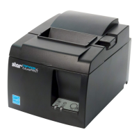
Do you have a question about the Star Micronics SP500 Series and is the answer not in the manual?
Detailed steps for unpacking the printer unit and verifying included accessories.
Tips for optimal printer placement, considering environmental factors and power.
Precautions for safe handling of the printer to prevent damage and ensure longevity.
Guidelines for maintaining the printer's condition and proper cleaning methods.
Steps for connecting USB and Ethernet cables, including ferrite core installation.
Detailed procedure for affixing the ferrite core and routing the USB cable.
Instructions for installing the ferrite core and connecting the Ethernet cable to the printer.
Guidance on connecting peripheral devices like cash drawers using a modular plug.
Steps for connecting the power cord, verifying voltage, and proper grounding.
Procedure for powering on the printer and checking the POWER lamp status.
Instructions on how to attach the rear cover if it is necessary.
Diagrams showing the correct routing and installation of connected cables.
Guidance on installing the switch blind to prevent accidental power switch operation.
Specific procedures for loading ribbon and paper into the Tear Bar model.
Step-by-step guide to opening the cover and inserting the ribbon cartridge.
Steps for loading roll paper, including cutting the edge and feeding it into the printer.
Specific procedures for loading ribbon and paper into the Auto Cutter model printer.
Steps for opening the cover, raising the auto cutter, and loading the ribbon cartridge.
Instructions for loading roll paper into the Auto Cutter model, including using the FEED button.
Guide for installing the roll paper guide for 58 mm width paper rolls.
Step-by-step instructions on how to clear paper jams from the printer.
Details on the POWER lamp, FEED button, and ERROR lamp on the control panel.
Table summarizing indicator states for power and error conditions.
Lists recoverable error types, their symptoms, and recovery conditions.
Lists non-recoverable error types and their symptoms.
Overview of the four available adjustment modes for printer calibration.
Explanation of the Self Printing Mode for testing printer functions and settings.
Describes the Hexadecimal Dump Mode for checking data transmission to the printer.
Lists the available interface types for the printer, such as USB and Ethernet.
Details the power supply input voltage, frequency, and consumption current.
Lists optional interface board units available for the printer.
Table detailing the function of each DIP switch and their factory preset values.
Technical specifications for the USB interface, including speed and connector.
Specifications for the Ethernet interface, including protocols and connector details.
Specifications for the Wireless LAN interface, including communication media.
Schematic diagram and notes for the recommended drive circuit for peripheral units.
| Brand | Star Micronics |
|---|---|
| Model | SP500 Series |
| Category | Printer |
| Language | English |
