– 31 –
TYPE
ONLY
D
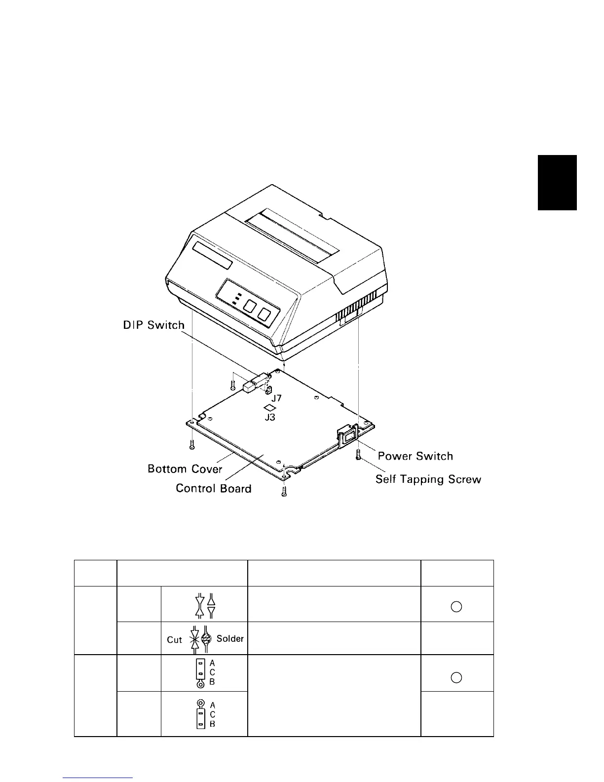
8-4. Jumper Setting
The serial interface is set to the RS-232C mode upon shipment from the factory.
When using in the 20mA current loop mode, it is necessary to set the jumpers.
The jumpers built into the Control Board allow for setting of functions shown in
the table. However, the Bottom Cover must be removed to perform this setting.
For setting the Jumper, disconnect the power source beforehand.
8-4-1. Removal of the Bottom Cover
Figure 8-4. Removal of the Bottom Cover
8-4-2. Setting of Jumper
Jumper
Setting Function
Factory
No.
Setting
OPEN RS-232C
J3
SHORT Current Loop
A-C
J7
B-C
Selection of Current Loop
Output (between TTY-TXD and
TTY-TXDR) Signal Polarity
(inversion possible) Consult
STAR MICRONICS for details.
 Loading...