– 13 –
GB
1. About this document
Please read carefully and keep in a safe place.
– Under copyright. Reproduction either in whole or
in part only with our consent.
– Subject to change in the interest of technical
progress.
Symbols
Hazard warning!
...
Reference to other information in
the document.
2. General safety precautions
Disconnect the power supply before
attempting any work on the unit.
• Installing these lights involves work on the mains
voltage supply; installation must therefore be
carried out professionally in accordance with the
applicable national wiring regulations and electri-
cal operating conditions (e.g.: DE: VDE 0100,
AT: ÖVE/ÖNORM E 8001-1, CH: SEV 1000).
• The floodlight enclosure heats up when the light
is on. Only adjust the angle of the LED head
once it has cooled down.
• The light must be positioned so that it is not
expected that anybody can look into the light
for any prolonged period from a distance of less
than 0.3 m.
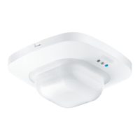
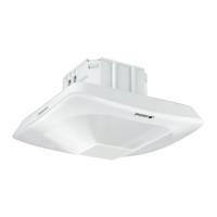
3. XLEDPROSquare XL S/ Wide XL S
Proper use
– Sensor-switched floodlight with LEDs as light
source.
– Suitable for wall mounting outdoors.
– Data line (D-line, optional) for synchronous
switching.
Non-intended use
– The sensor-switched LED floodlight cannot be
dimmed.
Not dimmable
Operating principle
The XLEDPROSquareXLS and XLEDPRO
WideXLS sensor-switched LED floodlights are
fitted with infrared sensors. These floodlights
provide a basic brightness function by means of
additional light lines.
In stand-alone mode, the slave version of this LED
floodlight must be switched ON and OFF via a
switch/button to be provided on site. As an option,
main and basic light can be switched ON and OFF
in synchrony via an additional data line (D-line)
between sensor-switched LED floodlights (master-
master) and slave LED floodlight (master-slave).
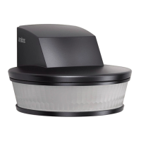
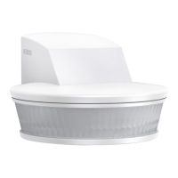
Models
– XLEDPROSquareXLS
– XLEDPROWideXLS
Package contents
XLEDPROSquareXLS (Fig. 3.1)
XLEDPROWideXLS (Fig. 3.3)
Product dimensions
XLEDPROSquareXLS (Fig. 3.2)
XLEDPROWideXLS (Fig. 3.4)
Product components (Fig. 3.5)
A Floodlight head
B Basic light level LED
C Enclosure
D Function setting
- Basic light level
- Time setting
- Twilight setting
E Status LED
F IR sensor
G Cover on controls
H Wall mount
I Plug connection
Luminous intensity distribution (Fig. 3.6 - 3.7)
4. Electrical connection
Connecting the mains power supply lead
(Fig. 5.5)
The mains power supply lead is a 3-core cable:
L = phase conductor
(usually black, brown or grey)
N = neutral conductor (usually blue)
PE = protective-earth conductor (green/yellow)
D = D-line (data line) optional
GB
 Loading...