FLIGHT MANUAL TSA-M, VARIANT S6
Doc.-No.: P400-006.000 E Page: 7-28 Revision: 6
Date of Issue: 07. October 2008 Date of Rev.: 26.09.2011
Information about the Liquid-Cooling-System:
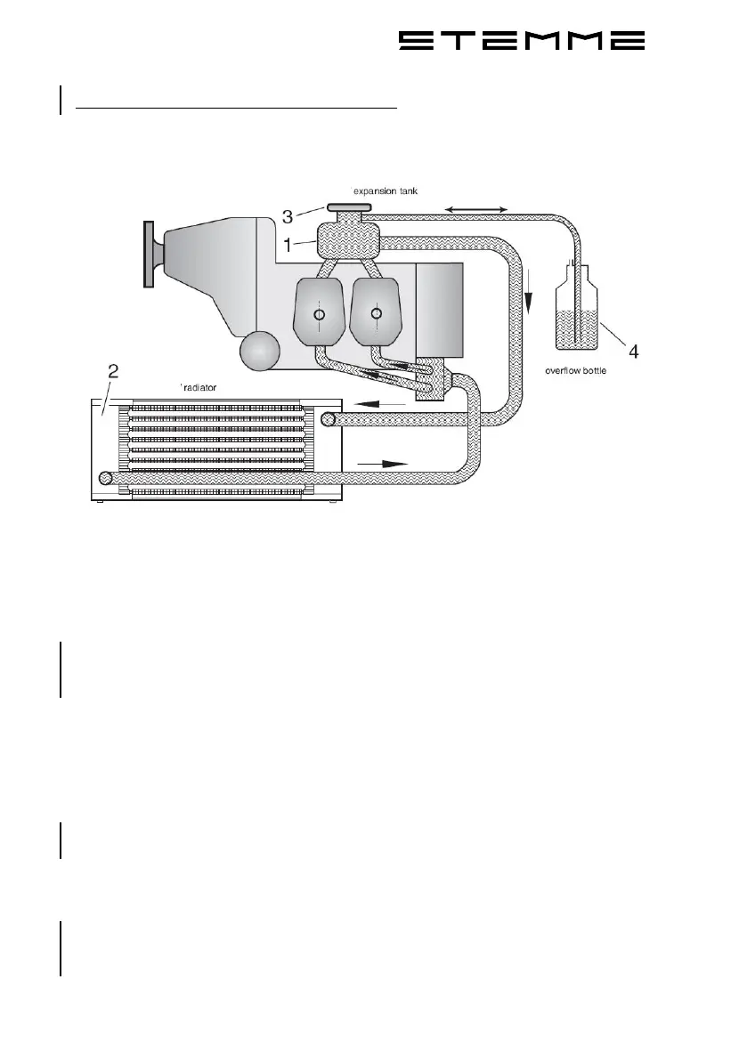
The following illustration shows the schematics of the liquid-cooling-system:
Illustration 7-5: Schematics of the Liquid-Cooling-System
(Illustration by ROTAX)
1. Expansion-Tank
The expansion-tank (1) is located at the top of the engine. It has a
overpressure-valve and breather-valve which lead to the overflow-bottle (4).
The coolant level in the expansion-tank has to be checked with every Daily
Inspection and refilled up to max. amount (up to top of tank) if necessary.
2. Radiator
the radiator (2) is located at the bottom of the central steel-tube-framework.
It is supplied with ram-air through the lower center NACA-cooling-inlet.
3. Filling-Hole
The filling-hole (3) for the expansion-tank (1) is located on top of the
expansion-tank (1). It is covered with a lid which closes the hole in a
pressure-resistant manner. This is where the cooling-system is filled and
refilled if necessary.
4. Overflow-Bottle
The overflow-bottle (4) is located at the left side behind the engine, near the
rear engine-suspension. It is designed as a fluid-buffer when the coolant
expands. The coolant level at the overflow-bottle (4) is checked before
every flight. If necessary, refill coolant until coolant-level at overflow-bottle is
between „min.“ and „max.“ again.