EasyManuals Logo

StepperOnline CL57RS User Manual

Default Icon
63 pages
To Next Page IconTo Next Page
To Previous Page IconTo Previous Page
Page #19 background imageLoading...
Page #19 background image
- 12 -
CLRS Series RS485 Closed Loop Stepper Drive User Manual
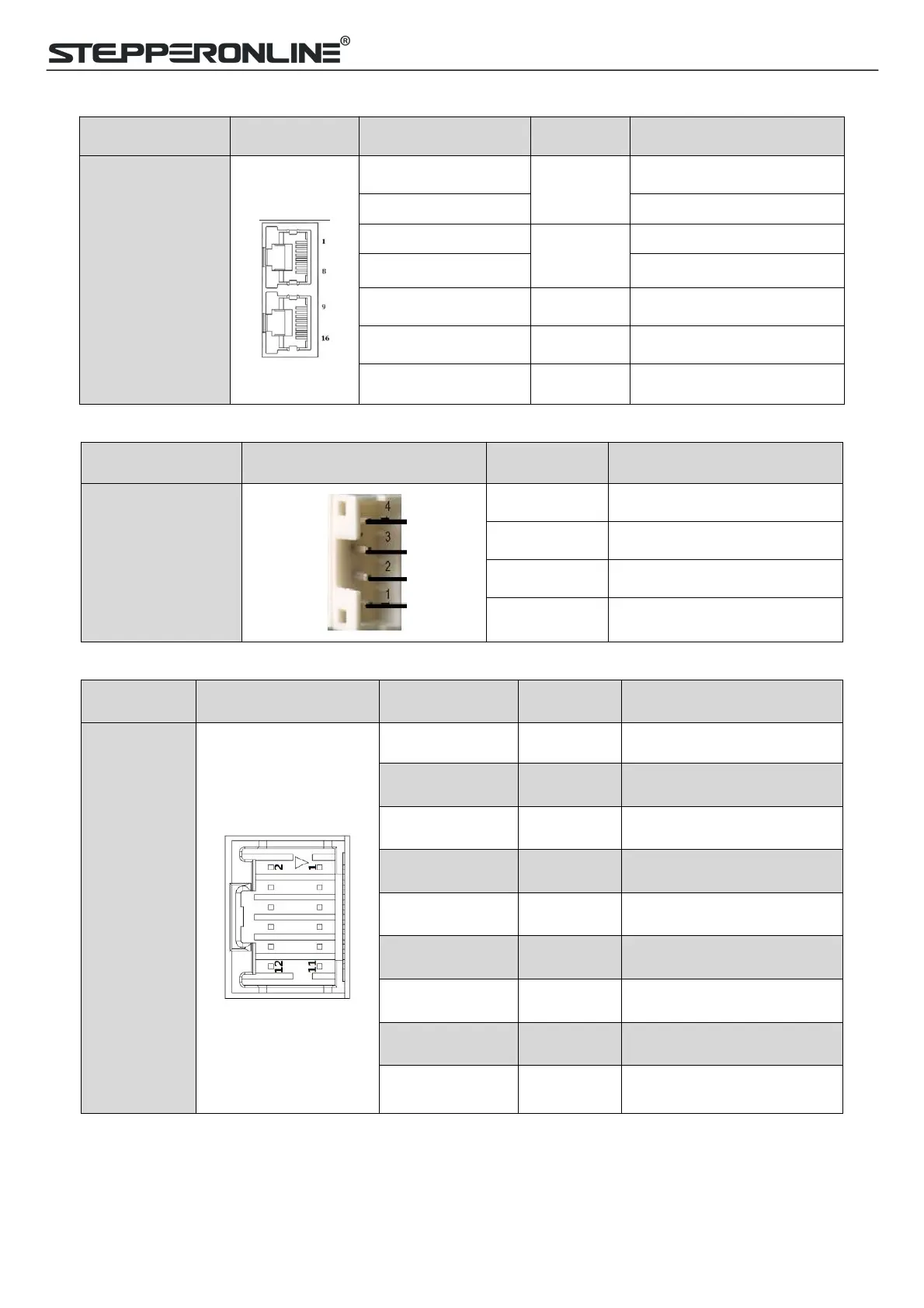
3.3.4 CN4-RS485 Communication Connector
Name
Pic
PIN
Signal
Description
CN4
1
RS485+
RS485 TxD+
9
RS485 RxD+
2
RS485-
RS485 TxD-
10
RS485 RxD-
5, 6, 13, 14
GND
GND
7, 8, 15, 163, 4, 11, 12
NC
Received
Connector cover
PE
Shield GND
3.3.5 CN5-RS232 Tuning Port
Name
Pic
PIN
Signal
CN5
1
NC
2
TxD
3
GND
4
RxD
3.3.6 CN6-Encoder Input Signals Connector
Name
Pic
PIN
Signal
Description
CN6
1, 2, 3, 4
NC
Reserved
5
EA+
Encoder signal of phase A+
6
EA-
Encoder signal of phase A-
7
EB+
Encoder signal of phase B+
8
EB-
Encoder signal of phase B-
9
EZ+
Encoder Z+ signal (optional)
10
EZ-
Encoder Z- signal (optional)
11
VCC
Encoder +5V voltage
12
GND
Encoder ground
3.3.7 DIP Switches
The CLRS series drives use an 8-bit DIP switched to set Salve ID (also called Site Alias), Baud Rate and Terminal
Resistance, they are shown as below:

Table of Contents

Questions and Answers:

Question and Answer IconNeed help?

Do you have a question about the StepperOnline CL57RS and is the answer not in the manual?

StepperOnline CL57RS Specifications

General IconGeneral
BrandStepperOnline
ModelCL57RS
CategoryDC Drives
LanguageEnglish

Related product manuals