9-2
P093932-203 Equipment Manual Illustrated Parts Breakdown
9.2 How To Use The
Illustrated Parts
Breakdown
1. Determine the function and application of the part required.
Examine the list of illustrations and select the most appropriate
title. Note the illustration page number.
2. Turn to the page indicated and locate the desired part on the
illustration (see Figure 9-1).
3. From the illustration, obtain the item number assigned to the part
desired. Refer to the accompanying description for specific
information regarding the part (see Figure 9-1).
4. The abbreviation A/R means “As Required” or “Amount
Required.”
5. The abbreviation SS means “Stainless Steel.”
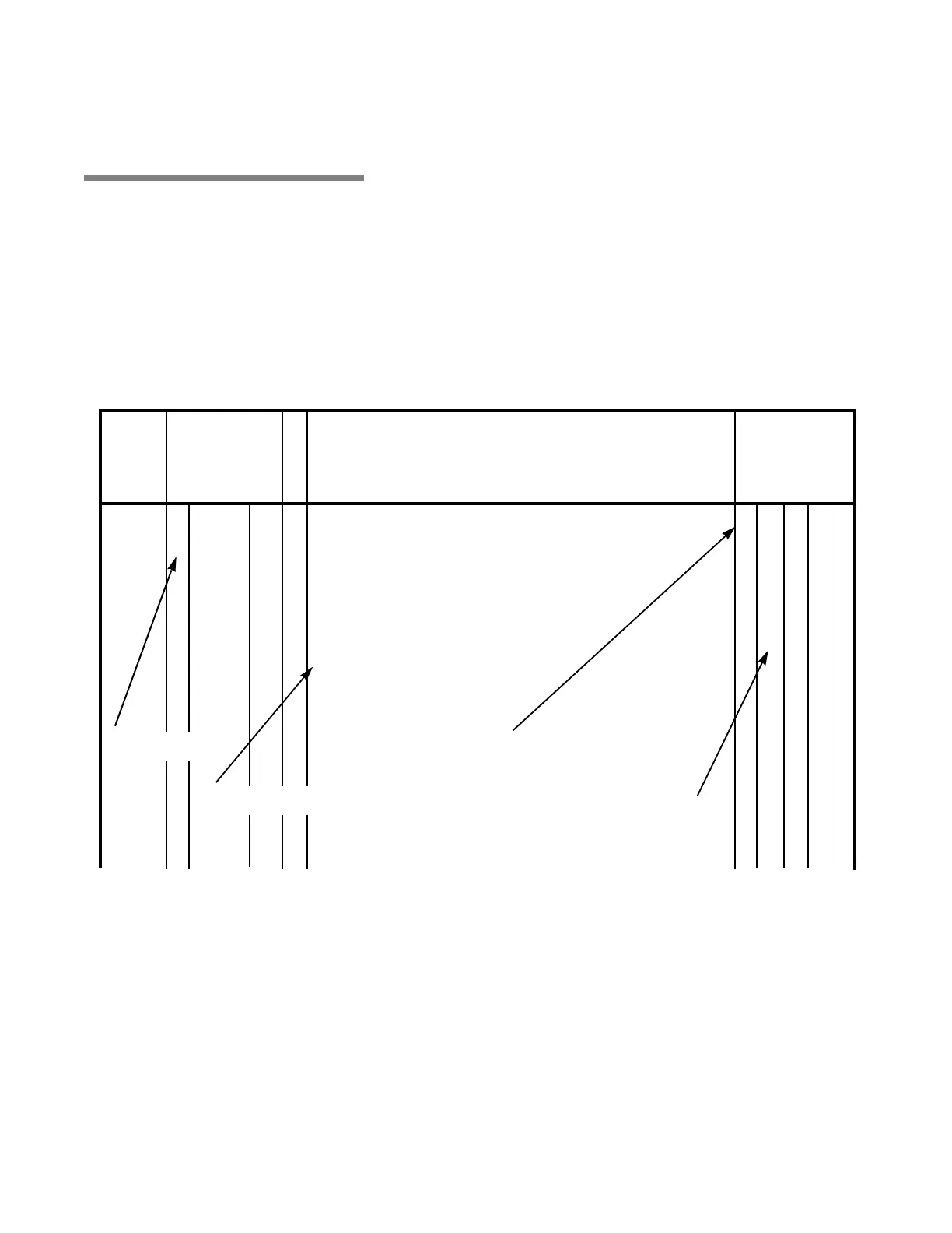
Figure 9-1. How to Use IPB Page (Typical)
DESCRIPTION
PART
NUMBER
UNITS PER
ASSEMBLY
FIG. &
ITEM
NO.
S
V
C
10-1 P 146667 035 Harmony LA Wall Control Assembly, Domestic............................. X
P 146667 327 Harmony LA Wall Control Assembly, Global.................................. X
P 146667 358 Harmony LA Wall Control Assembly, LA2 ...................................... X
1 P 146667 278 ASSEMBLY, Cover/Membrane Replacement .................................... 1 – – 1
2 P 042631 045 SCREW, Socket Button Head, 1/4-20 ................................................. 4 – – 4
3 P 076230 091 WASHER, Lock, 1/4 External Tooth.................................................... 4 – – 4
4 P 146667 087 COVER................................................................................................ 1 X 1 –
P 129382 215 • SCREW, Hex Head, 1/4-20 x 1/2...................................................... – 1 – –
P 129382 219 • WASHER, 1/4 ................................................................................... – 1 – –
5 P 143356 211 REFLECTOR....................................................................................... 1 – 1 –
No indention-part of top assembly
One indention-first subassembly,
part of assembly under which it is
identified with an “X” in the column.
One indention-first subassembly, part
of assembly under which it is indented.
No indention-part of
top assembly