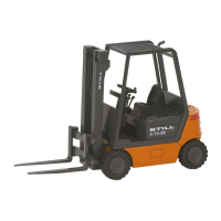
The document is a workshop manual for STILL R70-16, R70-18, and R70-20 Compact LPG and Diesel Fork Trucks. It is an electronic documentation system (STEDS) providing detailed instructions for maintenance and service.
The manual covers several functional groups, including:
Frame and Counterweight (Functional Group 01)
Function Description:
The frame of the forklift is a welded steel unit construction, designed for durability and stability. A cast iron counterweight is bolted to the rear of the frame, providing necessary balance for lifting operations. The hydraulic oil tank is integrated into the frame structure, serving as a cross-member located beneath the floor plate. This design integrates essential components, contributing to the overall structural integrity and compact nature of the truck.
Important Technical Specifications:
- Counterweight Bolt Torque: The three hex head bolts (M 24 x 85 / 8.8) securing the removable rear counterweight to the frame must be torqued to 660 Nm. Spherical washers and ball cups are used to ensure proper seating and load distribution for these bolts.
- Counterweight Weight:
- For models 7052/7054: 940 kgs
- For models 7056/7058: 1080 kgs
Usage Features:
The counterweight is removable, which may be necessary for certain maintenance procedures or to adjust the truck's configuration. The design emphasizes robust construction, ensuring the frame and counterweight can withstand the stresses of heavy-duty forklift operations.
Maintenance Features:
- Counterweight Removal/Installation: The manual provides instructions for securing the counterweight with specific torque values, which is critical for safety and operational stability.
- Jacking Up the Truck: Detailed safety precautions are provided for jacking up the truck.
- CAUTION: Always apply the parking brake before jacking.
- The truck must be positioned on level ground and secured against slipping or rolling.
- Only jacks of suitable capacity should be used.
- Jacking points are specified: beneath the mast (right or left) and beneath the frame (front or rear).
- WARNING: Never jack up the truck at the rear counterweight.
- Safety rules for maintenance and service jobs on the mast must be observed when jacking.
Steer Axle (Functional Group 02)
Function Description:
The steer axle is an articulating component suspended from the counterweight by two neoprene blocks, allowing for flexibility and smooth steering. The stub axles are supported within the axle beam by tapered roller bearings. Steering movement is precisely limited by stop screws on the stub axles. The steer axle is critical for directional control of the forklift.
Important Technical Specifications:
- Wheel Lock Angle: 80 - 82°
- Toe-in: 0 ± 1 mm
- Wheel Camber: 0°
- Trail: 0°
- Torque Loading:
- Wheel Hub: MA = 145 Nm
- Wheel Nuts: MA = 210 Nm
- Axle Bearings: MA = 195 Nm
- Steer Cylinder Fixing: MA = 210 Nm
- Nut on King Pin: MA = 290 Nm
- Lubricants:
- Wheel Hub Bearings: Grease F to DIN 51825-KP2K-20 lithium soap based (or KP2K-30 lithium soap based). STILL Ident No. 148659.
- Stub Axle Bearings: Grease FL to DIN 51825 - KPF2N-20, lithium soap based.
- Press Force for Track Rod Pins:
- Cylinder end: max. 21 kN
- Stub axle end: max. 26 kN
Usage Features:
The steer axle's design allows for precise steering angles, crucial for maneuverability in various operating environments. The use of neoprene blocks for suspension helps absorb shocks and vibrations, contributing to operator comfort and component longevity.
Maintenance Features:
- Steer Axle Removal/Installation:
- CAUTION: Remove the steer axle only with the mast in position on the truck to prevent tipping.
- Requires applying the parking brake, chocking front wheels, slackening steer wheel nuts, jacking up the rear at the counterweight, placing wooden blocks, removing wheels, and disconnecting hydraulic connections.
- CAUTION: Prepare for oil spillage when disconnecting hydraulic connections; catch oil in an adequate pan and dispose of it properly.
- Installation involves reversing the removal procedure, ensuring roll pin slots face the direction of forward travel, and torquing the 4 socket heads to 195 Nm.
- CAUTION: Do not swap hydraulic connections left and right.
- Wheel Hub - Removal/Dismantling/Reassembling/Installation:
- Detailed steps for slackening ball seat nuts, removing the wheel, pulling the hub cap, slackening the nut, removing the washer with the roll pin, withdrawing the hub, and removing sealing rings and bearings.
- Reassembly involves applying grease to sealing lips, repacking bearings with grease F (cavity between inner race and bearing cage, and bearing spaces marked 'x'), and tightening the nut to 145 Nm while rotating the wheel hub.
- Checking and Adjusting Steering Angles:
- The steering angle 'a' should be 80° - 82°. The complementary angle 'b' should be 98° - 100°.
- IMPORTANT: Ensure the wheel lock is limited by the stop screws (1) and not by the cylinder stroke.
- Adjustment is made by operating on stop screws (1) to set both steering angles to 80° - 82°.
- Checks include opposite angles and adequate clearance between wheels and the truck frame.
- Stub Axle - Removal/Dismantling/Reassembling/Installation:
- Steps include removing the wheel, pressing out the pin between the track rod and stub axle, slackening the nut, removing the washer, pressing down the king pin, removing the stub axle, and removing various components (spacing washers, O-ring, wiper rings, tapered roller bearings, spacer).
- Reassembly involves inserting the spacer, installing repacked tapered roller bearings with FL grade grease, applying FL grade grease to wiper rings, installing wiper rings, O-ring, and spacing washers, installing the stub axle into the axle beam, driving in the king pin (with a light smear of oil), fitting the washer, installing a new nut and tightening to 290 Nm, pressing the pin into the track rod, and installing the wheel.
- Lubricating the Steer Axle:
- Lubricate with FL grade grease using a grease gun until fresh grease oozes out at the lubricating points.
- Operate the linkage during greasing while the steer axle is off-load.
- NOTE: When lubricating the upper bearing, grease need not ooze out of the upper sealing ring; it may escape from the bottom.
- Track Rod Removal/Installation:
- Involves removing roll pins (4) and pressing out pins (5) using a press.
- Installation reverses the procedure, with specific press forces for pins at the cylinder end (max. 21 kN) and stub axle end (max. 26 kN).
- Steering Cylinder Removal/Installation:
- Requires removing track rods and disconnecting hydraulic connections (after marking for identification).
- WARNING: Hydraulic oil may spill.
- Slacken the four fixing screws (1).
- Installation involves retightening fixing screws (1) to 210 Nm, reconnecting hydraulic connections, and installing track rods.
- CAUTION: Do not swap hydraulic connections.
- For dismantling/reassembling the steering cylinder, refer to F.G. 06.
Power Axle (Functional Group 03)
Function Description:
The power axle is responsible for transmitting power from the drivetrain to the wheels, enabling the truck's movement. It incorporates a double reduction gear and a differential to manage power distribution and speed differences between the wheels during turns.
Important Technical Specifications:
- Torque Loading:
- Power Axle Mounting Bolts: 195 Nm
- Axle Housing Mounting Bolts: 120 Nm
- Wheel Hub / Slotted Nut: 180+20 Nm
- Axial Clearance:
- Hollow Shaft: ± 0.05 mm at maximum
- Wheel Hub: 0.07 mm pre-load
- Wheel Hub: 0.21 mm slackness
- Grade of Grease: Lithium soap based grease
- Gearbox Oil:
- Capacity: approx. 2 litres
- Grade: SAE – 80
- Standards: MIL-L-2105, API-GL 4
Maintenance Features:
The manual outlines procedures for:
- Power Axle removal and installation.
- Double reduction gear and differential (sectional view and exploded view are provided for detailed understanding).
- Axle housing installation.
- Half-shaft (axle shaft) removal and installation.
- Wheel hub removal and installation.
These sections provide comprehensive instructions for disassembling, inspecting, repairing, and reassembling the power axle components, ensuring proper function and longevity of the drive system. Specific torque values and clearances are critical for correct assembly and operation.