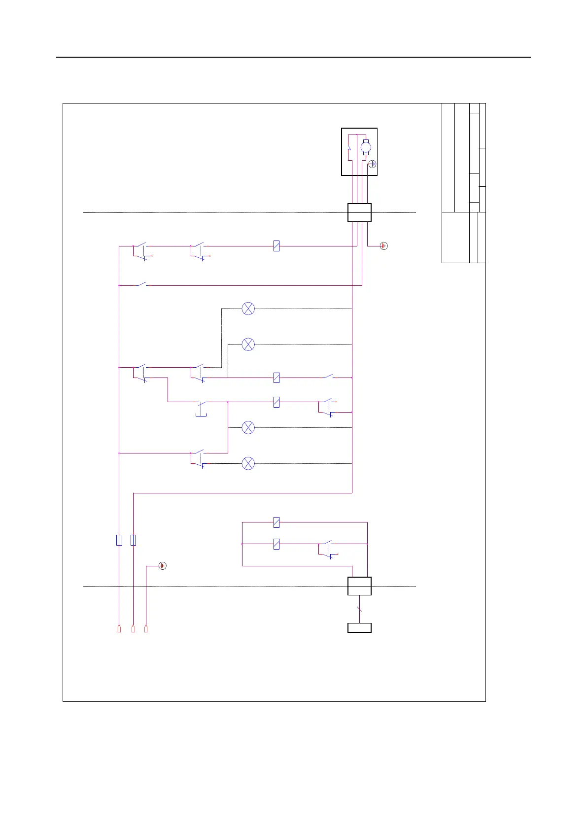
Cooli-1, Block Diagram
REV NOTES
100-240V
50/60Hz
All contacts are shown
under these conditions:
- un-powered
MPT / MPT
X2X3
INPUTS PUMPCONTROL BOX
Reset
button
Input from
main machine
Connector
for pump
Red
indicator
HL1
(Bimetal)
(Common)
(Motor)
(PE)
4
F1
F2
Pump
Machine
signal
relay
Reset
relay
Pump
enable
relay
(Control box
RESET)
Cable to the
main machine
Pump
supply
contactor
Green
indicator
HL4
(Pump
TURNED ON)
Overtemp.
relay
Green
indicator
HL2
(Control box
READY)
(Pump
NOT CONN./
OVER TEMP.)
Red
indicator
HL3
L
PE
N
Size
Scale
CAGE Code
DWG NO
Rev
Sheet
of
telephone: +45 44 600 800
Struers ApS
15763050
Monday, February 17, 2020
1 1
A2
Pederstrupvej 84
DK-2750 Ballerup
Denmark
A
Size
Scale
CAGE Code
DWG NO
Rev
Sheet
of
telephone: +45 44 600 800
Struers ApS
15763050
Monday, February 17, 2020
1 1
A2
Pederstrupvej 84
DK-2750 Ballerup
Denmark
A
Size
Scale
CAGE Code
DWG NO
Rev
Sheet
of
telephone: +45 44 600 800
Struers ApS
15763050
Monday, February 17, 2020
1 1
A2
Pederstrupvej 84
DK-2750 Ballerup
Denmark
A
K4
SB1
K5
K1.2
MOTOR AC
K2.1 K2.2
K3.2
K1
K5.2
K1.1
K5.1
K3K2
K4.1
BIMETAL
K3.1