PRODUCT DESCRIPTION & USE
LIGHT/ZOOM
The camera control unit has the ability to change the
function of the arrow buttons on the camera head. To
activate the zoom feature from the arrow buttons, place the
LIGHT/ZOOM switch (8) in the ZOOM position. To activate
the light level feature from the arrow buttons, place this
switch in the LIGHT position.
BUTTON FUNCTION
Place the BUTTON FUNCTION switch (9) ON to activate
the short pulse function (either zoom or gain) of the right
(‘W’) button on the camera head. Place this switch OFF to
deactivate the short pulse functions of the right camera head
button.
FLEX FILTER
The FLEX FILTER can be used to reduce the grid pattern
caused by a flexible scope (picture may blur). The Flex
Filter status can be toggled by changing the position of the
Flex Filter switch (10) or by pressing
both
enhancement
buttons (5) for at least one second. Graphics will indicate if
the Flex Filter is ON. Ensure the Flex Filter is OFF when
using rigid scopes.
AG FILTER
Position the AG FILTER switch (11) ON to reduce the
glistening or bright points of light caused by moisture
reflection. Position this switch OFF to deactivate the anti-
glistening (AG) filter.
SHUTTER SWITCH
Position the SHUTTER switch (12) ON/OFF to activate/
deactivate the automatic shutter.
ON: The camera automatically adjusts the brightness
of the video picture in response to varying light
levels without using an automatic light source.
OFF: The camera does not adjust to varying light
levels. You must use an automatic light
source to adjust picture brightness.
NOTE You may use an automatic light source and
the camera auto shutter at the same time,
but the camera auto shutter should normally
be used alone.
5
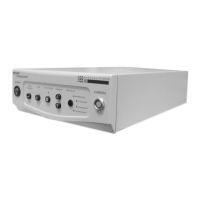
REAR PANEL CONNECTIONS
There are four analog and three digital video outputs on
the rear panel. Analog outputs include one RGB (19)
output, one NTSC Composite output, and two S-VHS
outputs (20,21). Digital outputs include one SDI output
(13) and two DVI outputs (14,15). The DVI outputs can
also display analog XGA outputs through a DVI-I to
VGA adapter. These are separate outputs and can be
used together or independently.
Additionally, there are two Remote outputs (17,18)
which can be used to control documentation equipment.
For more information about connecting the camera to
video peripherals, refer to the
INTERCONNECT
section in this manual.
There is also one interface connection (23) for the
Hermes Operating Room Control Center. For more
information about using the Hermes System refer to the
Hermes Operating Room Control Center Operating
Manual.
REMOTE ACCESSORY CONTROL
The camera supports two remote outputs (17,18) for
controlling a Stryker SDC Pro, VCR, or other video
accessory. The camera head button can activate one
or two peripherals.
In order to use the remote outputs to interface with
different peripherals, two six-foot cables with 3.5mm
diameter ends, one six foot cable with a 2.5mm and a
3.5mm diameter end and two 2.5mm-to-3.5mm
adapters have been provided.
Please refer to the
Interconnect
section in this manual.