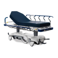
29” Litter Assembly with Scale System and Zoomr
91
Item Part No. Part Name Qty.
A 0003−355−000 Hex Hd. Cap Screw 8
B 0003−359−000 Hex Hd. Cap Screw 4
C 0007−071−000 Truss Hd. Mach. Screw 2
D 0004−330−000 Socket Hd. Cap Screw 4
E 0007−058−000 Torx Screw 4
F 0013−010−000 Ext. Tooth Lock Washer 5
G 0014−021−000 Washer 4
H 0015−027−000 Hex Jam Nut 4
K 0016−11 7 −000 Hex Lock Nut 4
L 0016−11 8−000 Hex Lock Nut 14
M 0023−283−000 Phillips Hd. Self−Tapping Screw 2
N 0023−288−000 Hex Washer Hd. Screw 2
P 0025−040−000 Rivet 20
R 0025−122−000 Rivet 2
T 0025−172−000 Rivet 4
U 0028−072−000 External Snap Ring 2
W 0721−031−065 Hole Plug 54
Y 0926−400−142 Bumper Wheel 4
AA 1001−040−012 Foot Board Receptacle 2
AB 1070−010−021 Trend Supt. Bracket, Right 1
AC 1070−010−022 Trend Supt. Bracket, Left 1
AD 1070−010−041 Trend Cross Support 1
AE 1070−012−011 Fowler Cross Supt. Bracket 1
AF 1070−017−011 Head End Load Cell Bushing 2
AG 1070−017−012 Foot End Load Cell Bushing 2
AH (page 101) Head End Lift Header Assembly 1
AJ (page 102) Foot End Lift Header Assembly 1
AK 1070−037−902 Display Template Label 1
AL (page 107) Display Assembly 1
AM 1210−800−008 Patent Label 1
AN 1211−030−018 Jack Support Bracket 2
AP 1211−030−044 Bumper Channel 2
AR 1211−030−046 Foley Bag Rack 2
AT 1211−031−031 Pneumatic Fowler Rest 2
AW 3000−300−113 Cable Tie 20
AY (page 28) Zoom Handle Assembly 1
BA 1040−050−131 Belly Tray 1
BB 1040−050−015 Zoom Display Label 1
BC 0029−007−000 Dual Lock 4
BD 0029−009−000 Dual Lock 4
BE 1040−500−002 Caution Label 1
BF 0016−006−000 Kep Hex Nut 2
BG 0005−022−000 Carriage Bolt 4
BH 0037−059−000 Hole Plug 1
BJ 1070−037−903 Specification Label 1
 Loading...