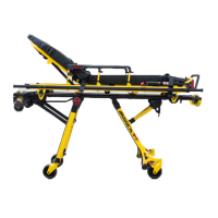
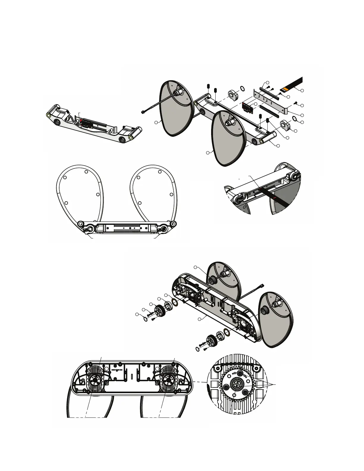
RRaaiill aasssseemmbbllyy,, ffoooott
5900200132 Rev C (right) (Reference only)
5900200133 Rev C (left) (Reference only)
2
3
1
38
4X
20
2X
31
2X
42
22
2X
43
2X
45
41
2X
44
CAM LOBE ORIENTATION (IDENTIFICATION MARKS FACE OUTWARD)
FLEX CABLE TO BE INSTALLED WITH
RED LABEL INDICATOR FLUSH WITH
END OF CASTING. ( 1/4")
CASTING CUT-AWAY
FOR CLARITY
ROUTE ARM CABLES UNDER
POSTS & CONNECT TO PCBA
4
2
2X
6
2X
5
2X
23
2X
32
6X
30
2X
C
ENTERLINE OF ARM
CENTERLINE OF ARM
INSTALL GEARS WITH ARROWS POINTING TO TOP SCREW
RELATIVE TO ARM CENTERLINE. TYPICAL BOTH ARMS.
START SCREWS IN THREADS - DO NOT TIGHTEN AT THIS TIME.
5900-009-002 Rev A.0 101 EN
 Loading...