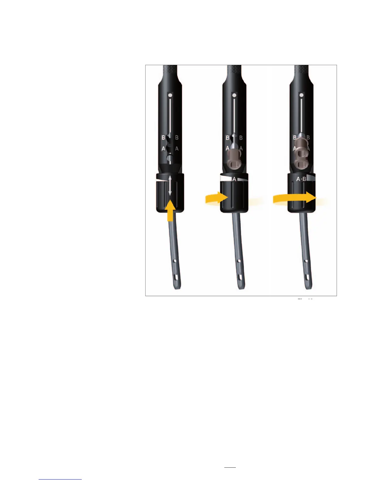
Fig. 18a Fig. 18b Fig. 18c
First, assemble the Knob to the Target-
ing Device by aligning the arrow on
the Knob with the white line on the
Target Sleeve, (Fig. 18a) then push
hard to click it.
By turning the Knob clockwise to the
position labeled (A), the sleeve inserted
in target (A) position, which is the
distal Recon Mode targeting hole, can
be locked. (Fig. 18b)
By further turning the Knob clockwise
to the position labeled (A+B), both
sleeves inserted in (A) and (B), which
are the both proximal and distal recon
mode targeting holes, can be locked.
(Fig. 18c)
Operative Technique
Assembly of Targeting Device