Do you have a question about the STS 1600 and is the answer not in the manual?
Explains symbols indicating safety risks, proper procedures, and recommendations for safe operation.
Provides safety guidelines regarding flammable liquids and general appliance usage.
Warns against using non-approved parts and highlights risks of improper installation or maintenance.
Lists key features of the Model 1600 shakers, such as heating, interfaces, and control systems.
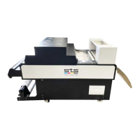
Identifies key components of the shaker unit, including switches, screen, and drawers.
Provides initial guidance on understanding the unit's automatic and manual modes before operation.
Explains the functions of the PLC touch screen, including automatic/manual modes and operational switches.
Details the monitoring interface, explaining sensor operations and belt status indicators.
Covers system parameter settings for dusting, heat, shaking, and belt speed adjustments.
Guides on correctly feeding media and explains the role of the vacuum and mesh belt systems.
Details terminal connections for the 220V AC power input and AC contactor.
Lists connections for Terminal 2, covering sensors, blowers, and paper roller components.
Outlines the power input and output specifications for the P1 power supply unit.
Describes Terminal 3 connections, including heating lamps and motor connections.
Details Terminal 4 connections for temperature control, paper feed, and rotary switches.
Shows PLC input/output assignments and communication port connections.
Provides connection details for relays Y7 (Suction), Y10 (Blow/Suction), Y11 (Dehumidification), and Y12 (Paper).
Provides connection details for heating relays (Y13, Y14, Y16, Y17) and drying relay Y6.
Details the connection locations for Relay Smoke Removal Y5.
Outlines the power input and output specifications for the P2 power supply unit.
Lists connections for the Microstep Drive, including power and control signals.
Details connections for Rotary/Emergency switches and Quick Connector.
Provides the physical dimensions of the STS 1600 Shaker unit for positioning.
Presents an overview of the electrical connections, specifying cable requirements.
| Brand | STS |
|---|---|
| Model | 1600 |
| Category | Paint Sprayer |
| Language | English |