7-32
Component Access / Removal
Built-In
Built-In
(600-
(600-
2
2
)
)
Series
Series
#3758407 - Revision B - August, 2006
Figure 7-80. Fan and Light Switch
Lower Switch Enclosure
Fan Switch
Light Switch
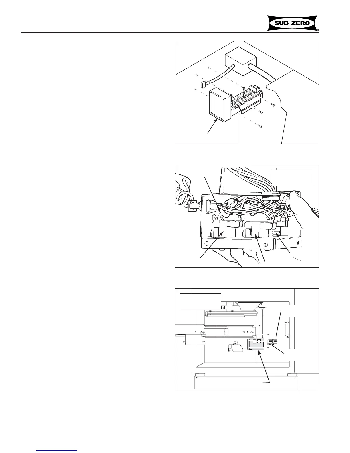
Figure 7-78. Icemaker
Icemaker
Icemaker Assembly (611-2, 611G-2, 650-2, 650G-2)
The icemaker assembly is attached to the left hand wall
of the freezer compartment with screws.
To remove the icemaker assembly (See Figures 7-78):
1. Extract screw at bottom left of icemaker.
2. Extract screws at top of icemaker.
3. Pull icemaker forward, disconnect electrical leads.
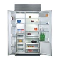
Freezer Light, Fan and Icemaker Switches
(611-2/611G-2,650-2/650G-2 Prior to Serial #2354455)
The freezer light, fan and icemaker switches are locat-
ed inside the switch enclosure at the top left rear corner
of the freezer compartment.
To remove a switch, the icemaker assembly should first
be removed, then (See Figures 7-79):
1. Extract screws securing switch enclosure to top left
rear corner of freezer compartment.
2. Lower enclosure, disconnect wire leads from switch
being removed.
3. Depress tabs on sides of switch and push switch
out of enclosure.
Freezer Compartment Thermistor
(611-2/611G-2,650-2/650G-2 Prior to Serial #2354455)
The freezer compartment thermistor is located inside
the switch enclosure at the top left of the compartment.
To remove it (See Figures 7-79):
1. Extract switch enclosure mounting screws.
2. Lower enclosure, then disconnect thermistor wire
leads from wire harness.
NOTE: On newer models the thermistor is hard-
wired to the control board, so it will be necessary to
cut the thermistor wires to remove it.
3. Extract screw which secures thermistor to inside of
enclosure.
Freezer Fan and/or Light Switch
(611-2/611G-2,650-2/650G-2 Start w/Serial #2354455)
The fan and light switches are in the lower switch
enclosure, which is attached to the left side wall.
To remove a fan or light switch, first remove the drawer
front assembly and the lower freezer basket, then (See
Figure 7-80):
1. Extract switch box mounting screws.
2. Flip switch box over and disconnect electrical leads.
3. Depress the tabs at back side of switch and push
switch from hole in switch box.
Starting w/Serial
#2354455
Figure 7-79. Switches & Compartment Thermistor
Thermistor
Icemaker Switch
Fan Switch
Light Switch
Prior to Serial
#2354455