7-27
Built-In
Built-In
(600-
(600-
2
2
)
)
Series
Series
Component Access / Removal
#3758407 - Revision B - August, 2006
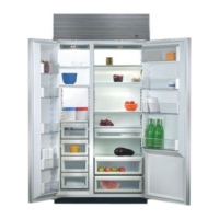
Figure 7-63. View of Compartment Top
Control Enclosure
Control Panel Assy
LCD
Evaporator
Fan Shroud
Evaporator Cover
Figure 7-64. Control Board
Tab
Tab
Forward Tabs
Ribbon
Cable
Control Board
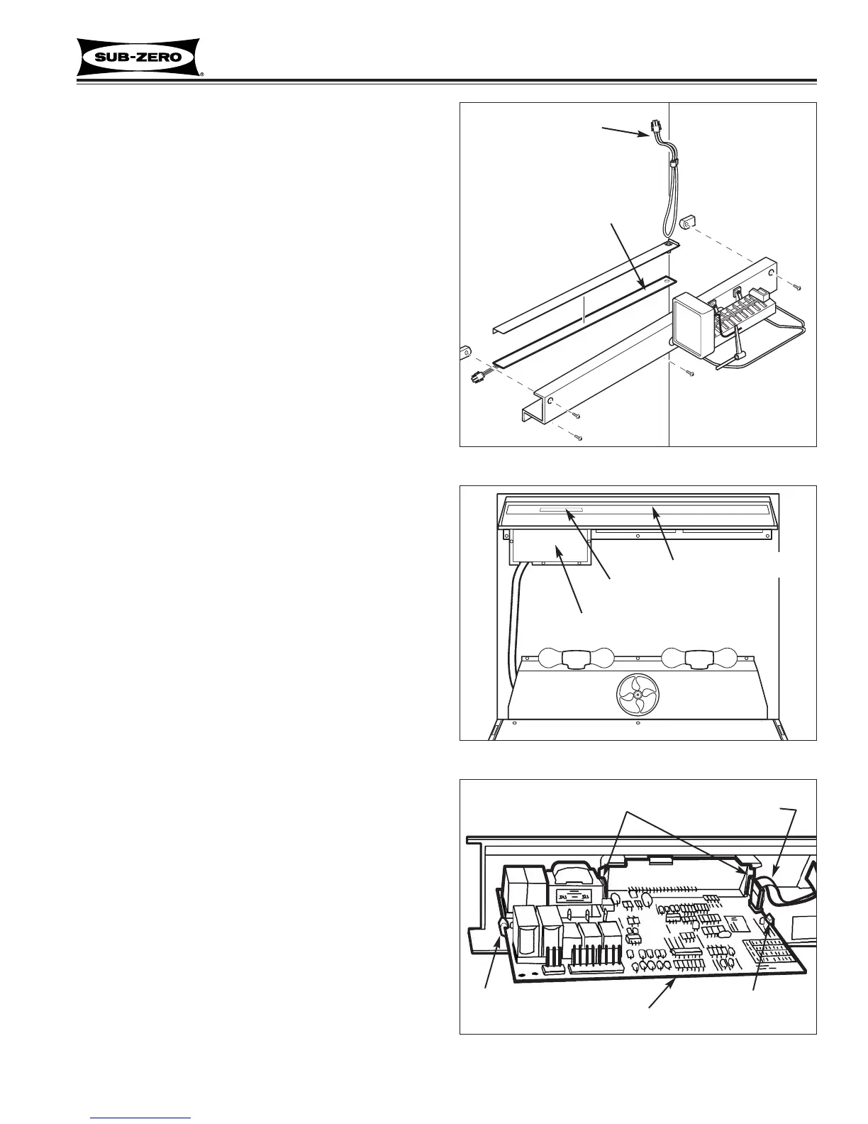
Freezer Drain Tube Heater (601F-2)
The braided wire drain tube heater is connected to the
wire harness behind the drain trough enclosure.
To remove the heater, drain trough enclosure must be
disconnected from back wall, then (See Figure 7-62):
1. Disconnect heater from wire harness
2. Extract clamp which holds heater in place, and pull
drain tube heater from drain tube.
NOTE: When replacing the drain tube heater, it is nec-
essary to insert it a minimum of 3" into the drain tube.
Drain Trough Heater (601F-2)
The drain trough heater consists of a braided wire
heater sandwiched between two strips of aluminum foil,
one of which has adhesive on the outside to hold the
heater to the bottom of the drain trough.
To remove the heater, drain trough enclosure must be
disconnected from back wall, then (See Figure 7-62):
1. Disconnect heater from wire harness
2. Peel heater from bottom of drain trough.
NOTE: When replacing the drain trough heater, bottom
of drain trough must be dry in order for heater to stick.
Control Board (601F-2)
The control board is held in position by two sets of tabs
behind the left side of the control panel assembly. The
two forward tabs position the LCD in the control panel
window, while the other two tabs secure the middle of
the control board. The control board is then shielded by
a control enclosure, and concealed by the light diffuser.
To remove the control board, the light diffuser must first
be removed, then (See Figures 7-63 and 7-64):
1. Extract screws securing control enclosure to ceiling
of compartment.
2. Lower back of enclosure while pulling it toward rear
of unit.
3. Disconnect all electrical leads from control board.
NOTE: Observe orientation of membrane switch
ribbon cable so it can be reconnected correctly.
4. Expand the two tabs at middle of control board out-
ward while pulling back of board down slightly.
5. Expand the two tabs outward that hold LCD.
6. Pull control board down and toward rear of unit.
Figure 7-62. Drain Trough and Drain tube Heaters
Drain Tube Heater
Drain Trough Heater