COMPONENT INFORMATION
2-11
EVAPORATOR SUMP
The evaporator sump area consists of the follow-
ing components.
• Evaporator/Heat Exchanger Assembly
• Evaporator Fan Motor Assembly
• Cal Rod Defrost Heater (700TC/I, 700TF/I,
700BF/I Only)
• Defrost Terminator (700TC/I, 700TF/I, 700BF/I
Only)
• Evaporator Thermistor
• Control Board Assembly (700BR, 700BF/I Only)
• Baffle Mount Assembly (700TC/I Only)
Sump Area Access
1. Remove both drawer assemblies.
2. Remove the lower mullion divider by pushing
up from underneath (Figure 2-23), then remove
both mullion divider supports (700TR &
700BR Only).
3. Remove the icemaker if applicable.
4. Detach all four drawer slides by extracting four
mounting screws (Figure 2-21).
5. Remove both drawer closers by extracting two
mounting screws (Figure 2-22).
6. Remove both reed switches by unscrewing the
mounting screw, tilt the top of the reed switch
assembly forward and disconnect the electrical
connector (Figure 2-17).
7. Remove three screws at the front and back of
the evaporator cover, then remove the evapora-
tor cover. Remove the air duct retaining screw
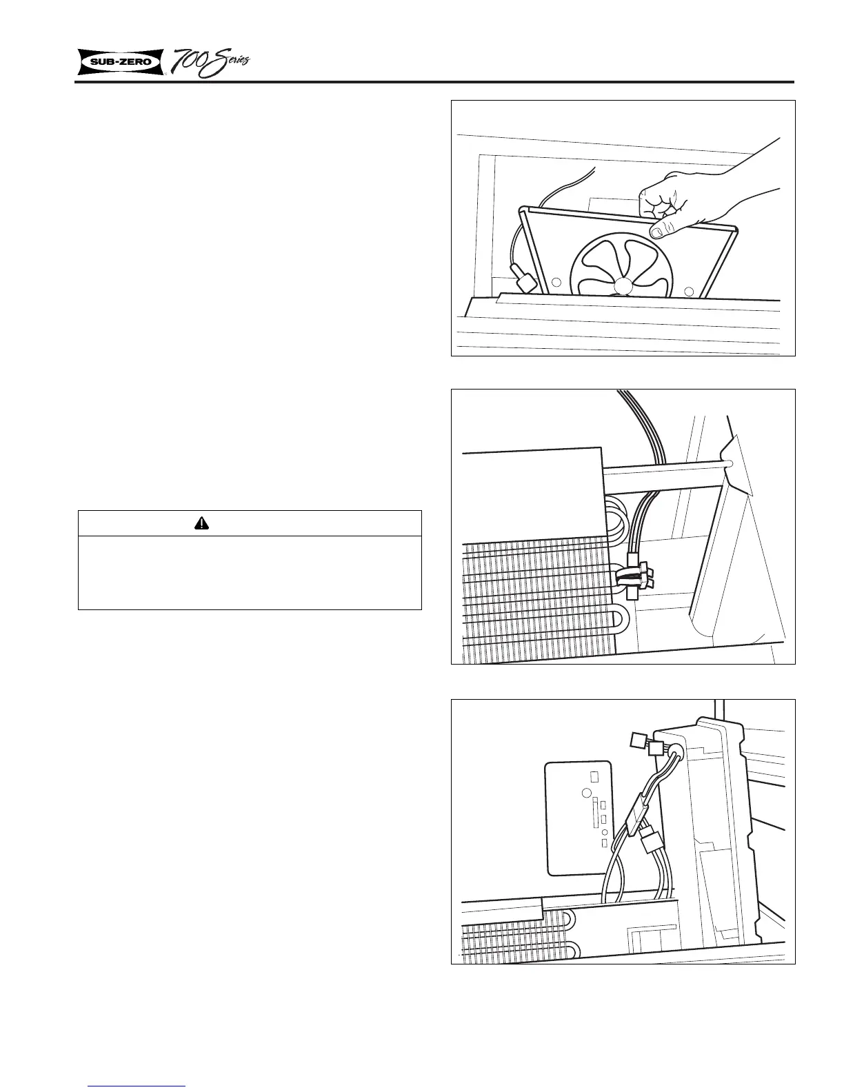
Figure 2-24. Evaporator Fan Motor Assembly
Figure 2-25. Evaporator
Figure 2-26. Microprocessor Assembly
Models 700TR, 700BR
CAUTION
The top drawer in the 700BR and 700 BF/I has a
control cable that must be disconnected before
drawer removal (See Drawer Removal Instructions).