COMPONENT INFORMATION
2-3
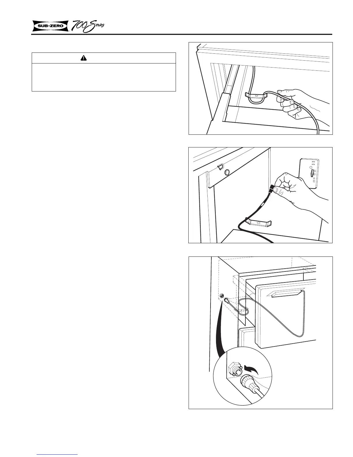
Drawer Removal and Installation
1. Base-Unit Top Drawer Removal:
a. Pull top drawer forward 6” to 10”, lift up
off of the pins at front. Continue to pull
drawer forward while pushing slide assem-
blies back. Then lie drawer face down,
directly in front of unit.
b. Disconnect display cable from left of rear
duct by turning counterclockwise and
pulling (Figures 2-4, 2-5 & 2-6).
2. Drawer Removal: To remove all other drawers,
pull drawer forward 6” to 10”, lift up off of the
pins at front. Continue to pull drawer forward
off of slide assembly (Figure 2-3).
3. Drawer Re-installation: Extend slide assem-
blies forward and lay drawer tub side flanges
over slide assemblies. From underneath, pull
slide assembly forward until pins at front line
up with drawer tub locating holes.
NOTE: Right slide assembly must be positioned
between right side drawer tub flange and peg at
back right corner of drawer assembly.
Figure 2-4. Display Cable
Figure 2-5. Display Cable
Figure 2-6. Display Cable
CAUTION
On 700BR and 700BF/I, the top drawer has a
control cable that must be disconnected before
drawer removal.