F Series Manual
16
2.2 Tool/knife calibration with ADC
The ADC works by interruption of a light beam. This is harmless for the tools. The sensor unit
on the right-hand side cover is used to measure the tools in slot 2 & 3. The sensor in the left-
hand side can measure the tools in slot 1.
The drag module, which moves low over the table, can’t pass over the ADC
sensor units. The drag module must be used in slot 1. If the left ADC sensor is
installed, the working area will be reduced when using the drag module in order to
avoid that the module hits the ADC sensor unit. The front margin is moved 80 mm
to the rear, so module 2 and module 3 can use the full table width.
2.2.1 General calibrations with the ADC
The down position of ADC controlled tools is set automatically each time the machine is
switched on or when a tool is changed. The down position is a value, relative to the table height.
The up position should be set manually. The up position is the relative distance from the down
position. Make sure the up position measures significantly more than your material thickness.
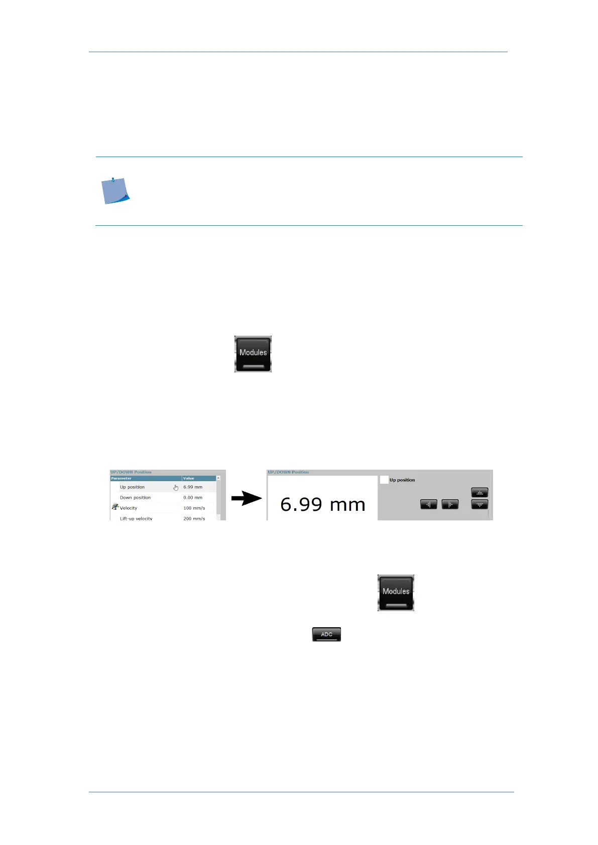
To set the up position, first click . If Axis Control is not automatically selecting the tool,
whose up position needs to be checked/set, click the picture of the corresponding module.
Click ‘Up position’ in Axis Control or press ‘Up’ on the remote. Press the down arrow until the
tip of the knife is about 4 – 5 mm above the material, then press apply. It is not necessary that
the material is on the table, the up position can also be set if the thickness of the material is
known. Just press the up/down arrow until the value is 4 – 5 mm higher than the thickness of
the material.
The origin, lateral and longitudinal parameters can also be set by the ADC. Those parameters
are material independent and should only be set during the first installation of a tool or when
there are quality issues.
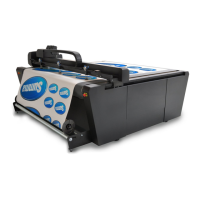
In order to automatically calibrate those parameters, first click . If Axis Control is not
automatically selecting the tool, whose tool calibration needs to be checked/set, click the
picture of the corresponding module. Then click . The ADC will now measure the three
parameters and store the values.