92 MODBUS Protocol
E500 Series Universal Low-Power Inverter
Appendix III: Brake resistor selection
In running process of inverter, in case that controlled motor speed falls too fast
or motor load shakes too fast, the electromotive force will charge inverter
internal capacitance through inverter in reverse direction, therefore, voltage at
two ends of power module will be boosted to damage inverter possibly. The
inverter internal control will be suppressed based on loading condition; in case
of brake performance failing to meet customer requirements, it’s necessary to
connect with external brake resistor to realize immediate release of energy. The
external brake resistor belongs to energy-consumption brake mode, which will
consume all energy on power brake resistor. Therefore, selection of power and
resistance value of brake resistor must be reasonable. The following content
refers to introducing brake resistor power and resistance value recommended to
be employed for SUNFAR inverter. Based on loading condition, user can
modify value properly in line with the range specified by SUNFAR inverter.
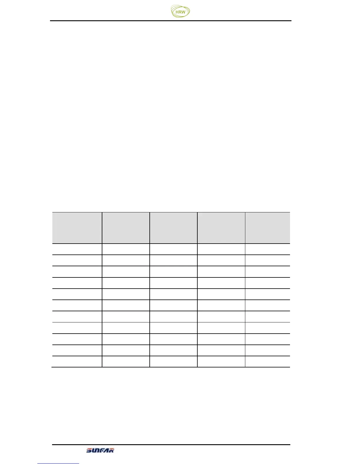
Inverter model
Applicable
motor (KW)
Brake resistor
power (KW)
Brake
resistance
value (Ω)
Braking
torque (%)
E500-2S0004
0.4 0.1 150 100
E500-2S0007
0.75 0.1 100 100
E500-2S0015
1.5 0.2 70 100
E500-2S0022
2.2 0.2 50 100
E500-2S0030
3.0 0.4 40 100
E500-2S0040
4.0 0.4 35 100
E500-4T0007
0.75 0.1 400 100
E500-4T0015
1.5 0.2 300 100
E500-4T0022
2.2 0.4 200 100
E500-4T0030
3.0 0.4 150 100
E500-4T0040
4.0 0.5 125 100