14 Function Parameter Table
E500 Series Universal Low-Power Inverter
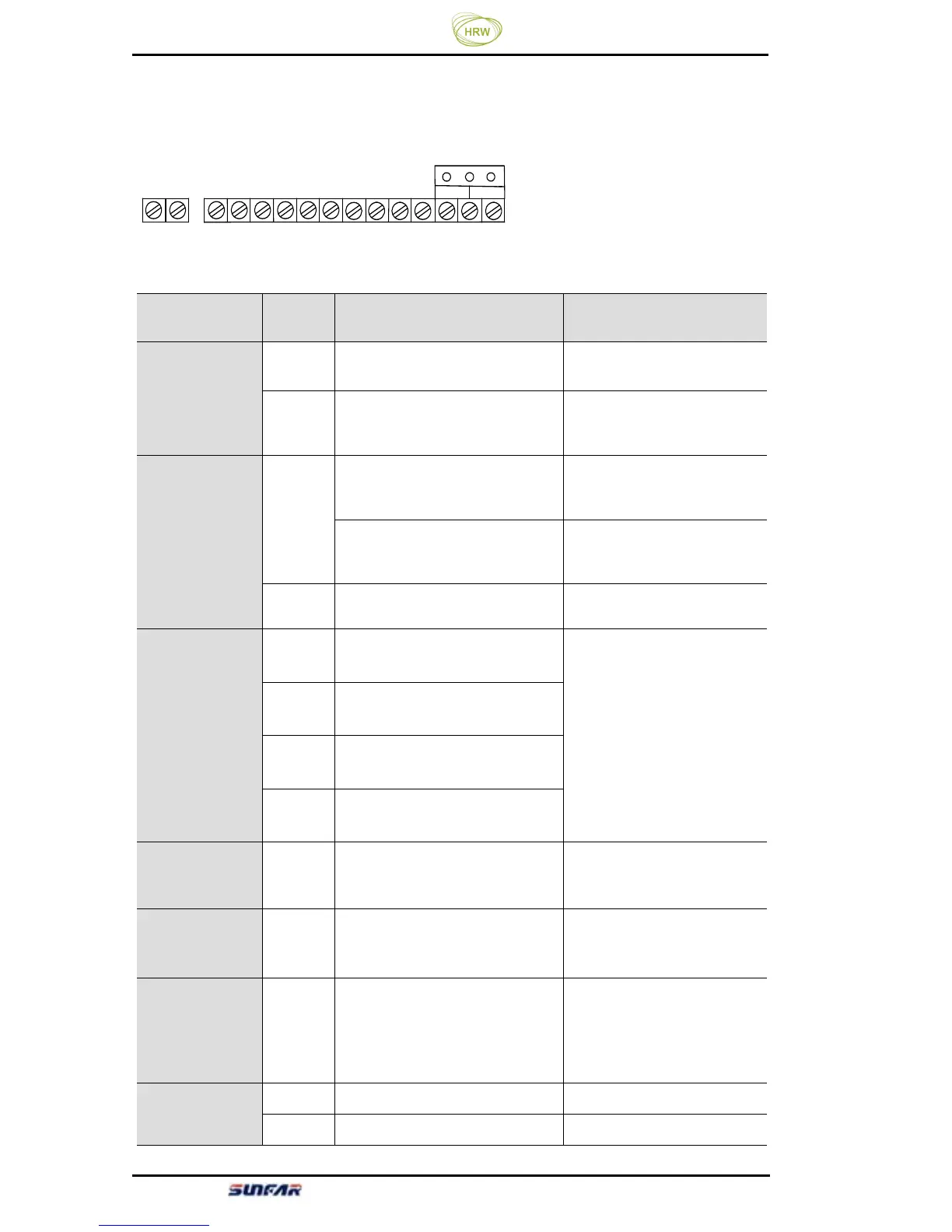
3.5 Wiring of control loop terminal
(1) Diagram of control loop terminal
TA
TC X1 X2 X3 X4 OC CM 24V VS AI AO GND RS+ RS-
AV
(2) Function description of control loop terminal
Type
Terminal
symbol
Terminal function Remarks
Power supply
VS
Externally providing +10V
(0~20mA) power supply
-
24V
External providing +24V
(0~50mA) power supply
(CM terminal is the power
-
Analog input
AI
Voltage signal input terminal
(when jumper terminal is
connected to V terminal)
Input range : 0~10V
Current signal input terminal
(when jumper terminal is
connected to A terminal)
Input range : 0~20mA
GND
Common port of analog input
signal (VS power grand)
-
Control terminal
X1 Multifunctional input terminal 1
①The specific function of
multifunctional input
terminal is to be set by
parameter [F1.08] – [F1.11],
effective when the terminal
and CM end is closed.
②X4 has function of pulse
width speed adjusting
(function code F1.11=0),
and PWM wave period is
set by F0.23.
X2 Multifunctional input terminal 2
X3 Multifunctional input terminal 3
X4 Multifunctional input terminal 4
Analog output AO
Programmable voltage signal
output terminal (external
voltage meter (set by [F1.05]
Voltage signal output
0-10V
OC
output
OC
Programmable open-circuit
collector output, set by
parameter [F1.13]
Maximum load current
150mA and maximum
withstanding voltage 24V.
Programmable
output
TA
TC
TA-TC normally open;
When TA-TC is closed,
effective
when parameter [F1.14] selects
output.
Contact capacity:
AC 250V, 1A resistive load
Communication
RS+ 485 communication port -
RS- 485 communication port -
Voltage/current input