Functional Details 39
E500 Series Universal Low-Power Inverter
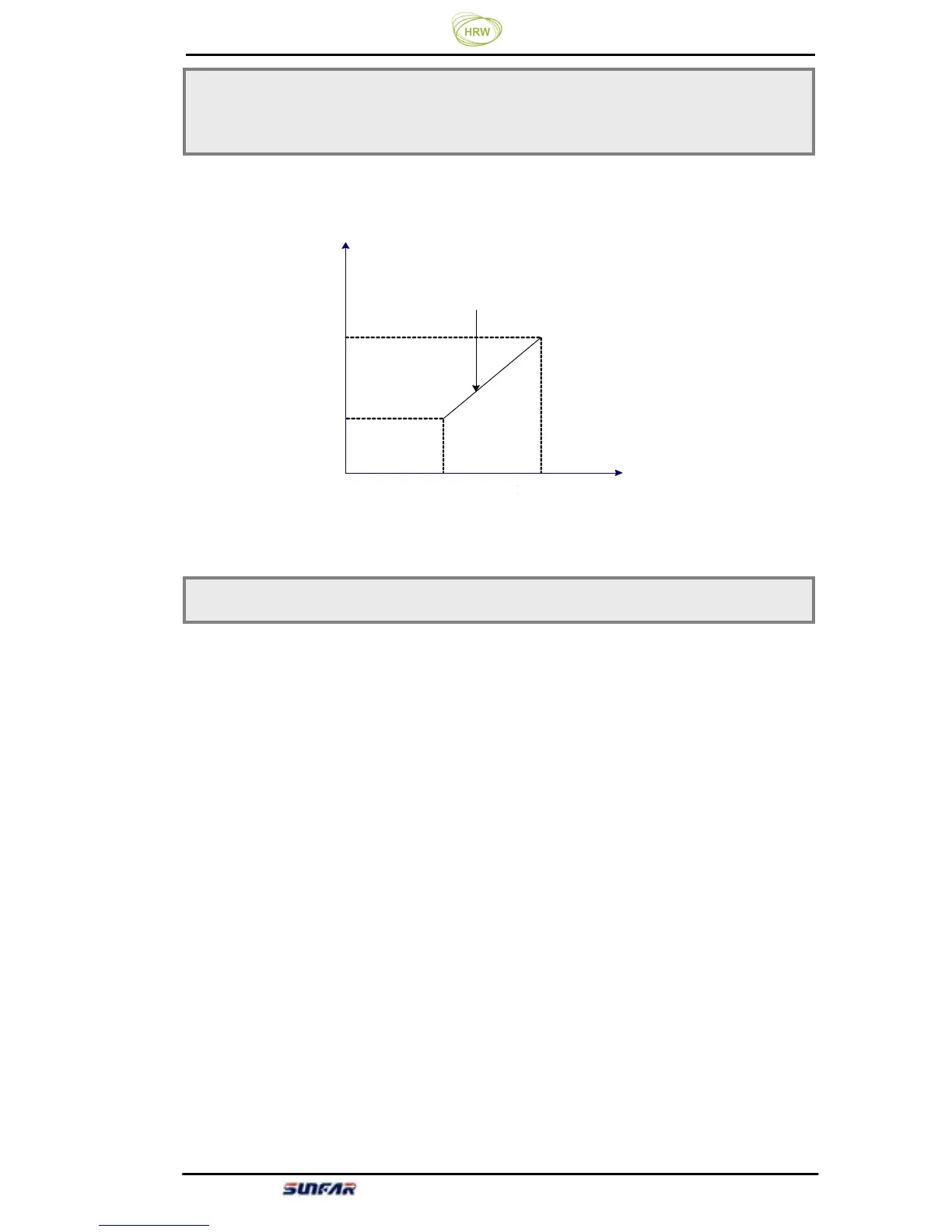
The corresponding relationship between the analog input quantity and set
frequency is shown in Figure 6-6.
Select the meaning of analog output terminal AO
(setting of fratile decimal
system).
LED Units: Define meaning of analog output AO
0: output frequency
The analog output (AO) amplitude is proportional to the inverter’s output
frequency. The setting upper limit of analog output ([F1.07]) is corresponding
to the upper limiting frequency.
1: output current
The analog output (AO) amplitude is proportional to the inverter’s output
current. The setting upper limit ([F1.07]) of the analog output is corresponding
to two times of the inverter’s rated current.
2: Output voltage
The analog output (AO) amplitude is proportional to the inverter’s output
voltage. And the setting upper limit ([F1.07]) of the analog output is
corresponding to the maximum output voltage ([F0.13]).
F1.05 Analog output selection Setting range: 0 ~ 2
Figure 6-6 Corresponding relationship sketch of analog input quantity and set frequency
F1.03 Minimum set frequency Setting range: 0.0Hz ~ [F1.04]
F1.04 Maximum set frequency Setting range: [F1.03] ~ [F0.04]
Frequency