40 Function Parameter Table
E500 Series Universal Low-Power Inverter
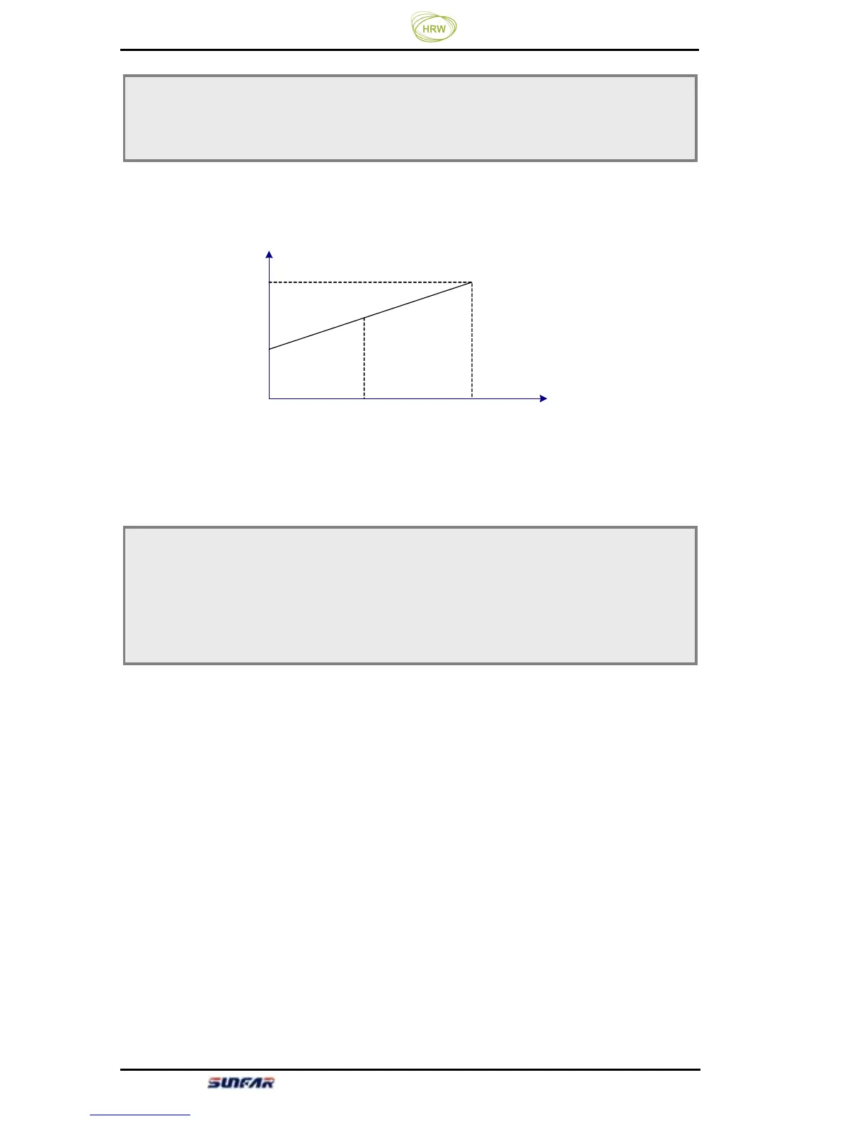
Define the maximum value and minimum value of analog output AO output
signal. Refer to figure 6-7.
Output
frequency
Output voltage
Output current
Upper limiting
frequency
Rate current
Max./rate
voltage
[F1.06]
0
1
2
Function definition of switch quantity input terminal X1 ~ X4, which is
described as below:
0: control terminal X1-X3 are as spare terminal,X4 as PWM pulse speed
control terminal
1: Multi-speed control 1
2: Multi-speed control 2
3: Multi-speed control 3
The combination of multi-speed control terminals can be used to select
multi-speed output frequency. The frequency setting at each stage is to be
determined by the multi-speed control parameter functional group ([F3.00]~
[F3.06]).
F1.06 AO output lower limit Setting range: 0.0 V ~ [F1.07]
F1.07 AO output upper limit
Setting range: [F1.06] ~ 10.0 V
Figure 6-7 Analog output content of analog output terminal
F1.08 Function selection for input terminal 1 Setting range: 0 ~ 29
F1.09 Function selection for input terminal 2 Setting range: 0 ~ 29
F1.10 Function selection for input terminal 3 Setting range: 0 ~ 29
F1.11 Function selection for input terminal 4 Setting range: 0 ~ 29
AO