5 Electrical Connection User Manual
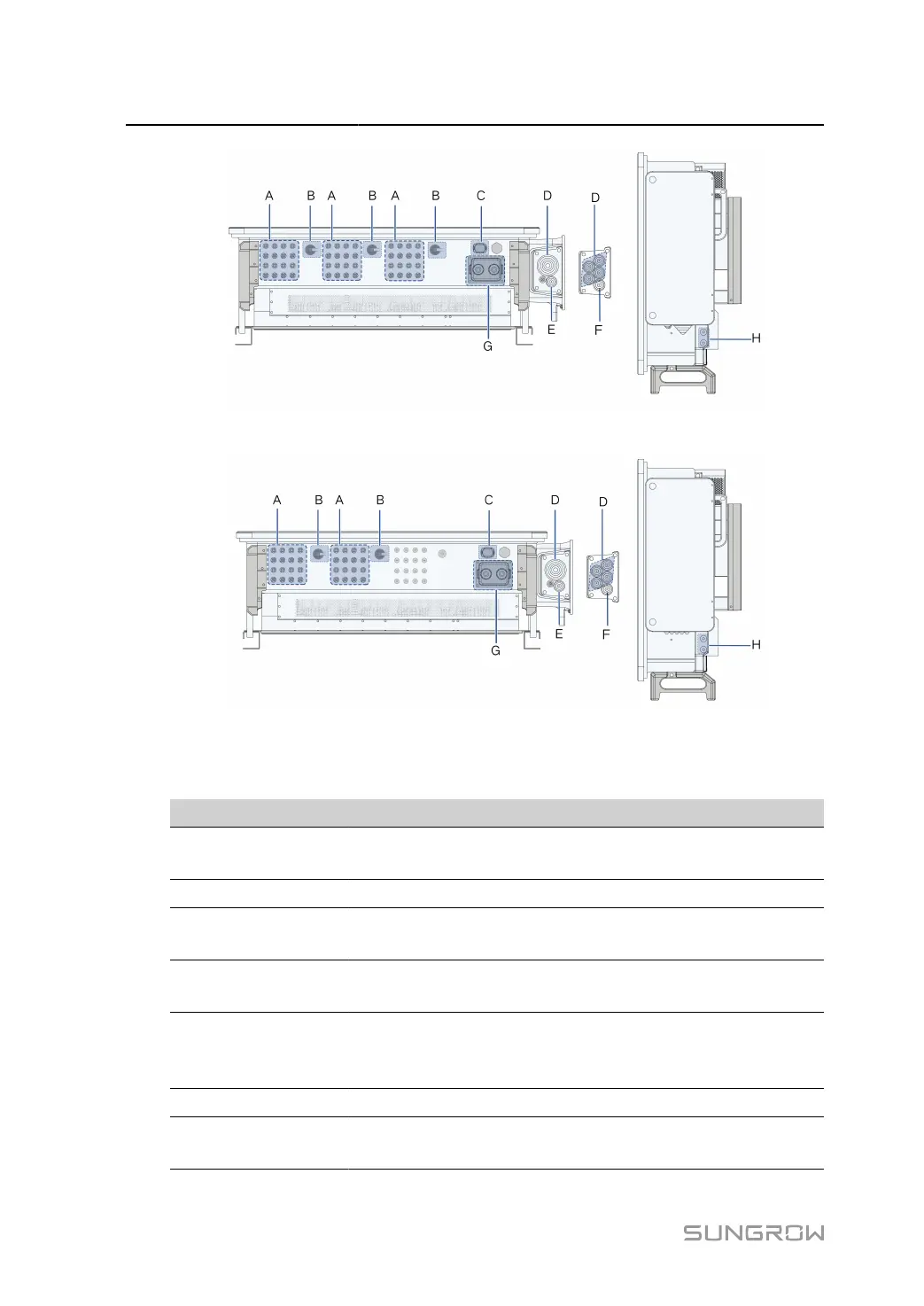
figure 5-1 Terminal Description(SG125/110CX-P2)
figure 5-2 Terminal Description(SG75CX-P2)
* The image shown here is for reference only. The actual product received may differ.
Item Terminal Mark Note
A PV terminals + / -
24 pairs of terminals(SG125/110CX-P2)
16 pairs of
terminals(SG75CX-
P2)
B DC Switch DC SWITCH Used to switch on and off the DC input.
C
Communica
tion terminal
COM3 For communication module connection.
D
AC wiring ter
minal
— Used for AC output cable connection.
E
Standby
grounding ter
minal*
— Used for internal grounding.
F PE terminal — Used for internal grounding.
G
Communica
tion terminal
COM1,COM2
RS485 communication, digital input/output DI/
DO, etc.
38