User Manual 6 Electrical Connection
47
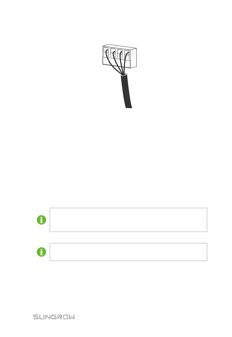
according to the marks on the configuration circuit board.
Step 3 According to the position of the inverter (refer to the prior section), repeat
step 1…2 to connect the other RS485 cables.
Step 4 Pull cables outwards to confirm whether they are fastened firmly.
Step 5 According to the position of the inverter (refer to the prior section), switch
ON or OFF the terminating resistor.
Step 6 Tighten the tread-lock sealing lock. Block off the vacant terminals to protect
the dust and moisture penetrating inside the inverter.
Step 7 Seal the gaps between the cable and the gland inside the lower part of the
cabinet by fireproofing mud. If there is no other connection procedure,
reassemble and fix the front cover of the connection cabinet.
Step 8 Connect the communication devices. Refer to other manuals and documents
if there are other devices.
Step 9 Confirm the communication connection and set the communication
parameters.
If more than one inverter is connected to PC or Logger, please set the
communication parameters from the LCD display. For more information,
please refer to 10.12 Communication Parameter Setting.
Logger 3000 and RS485-232 converter are optional parts and can be
ordered from Sungrow.
6.6 Configurable Dry Contact
There are Fault Alarm dry contacts and Emergency Stop dry contacts located on the
configurable circuit board.
 Loading...