14 • Questions? Call or Text +1-801-658-0015
Zapp
™
User Manual
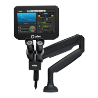
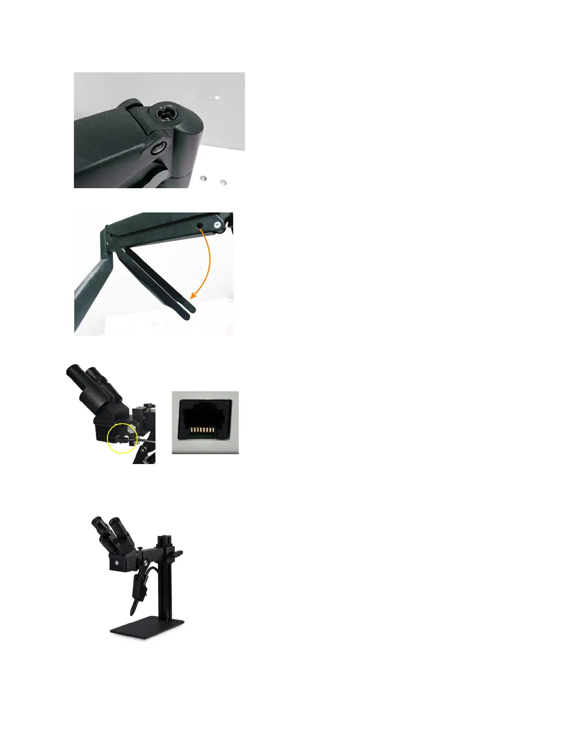
Figure 14.1. Adjust the tension of the Microscope Arm
Assembly for more loose or more tight movement.
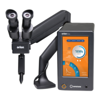
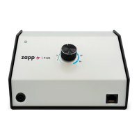
Figure 14.3. After installing the rubber eyepiece covers, use
the RJ45 Shutter Cable to connect the welder to the back
and bottom of the microscope head. The other end of the
cable connects to the port in the front of the Zapp Plus. (See
Figure 2.1)
• Attach the Angled Bracket (C) to the bottom of
the Microscope Arm Assembly (A) using three
shown in Figure 12.1.
• Lift and position the arm assembly onto the
table in the desired location.
• Run wood screws through the Mounting
Bracket (C) and into a vertical surface of the
table, as shown in Figure 13.4.
ARM TENSION ADJUSTMENT
The spring tension is factory pre-set, but should chang-
es be desired, the tension can be adjusted by turning a
hex screw located on the arm joint, as shown in Figure
14.1. Use the included 6mm Allen wrench to make
adjustments.
• Turn the hex screw counterclockwise (in the
direction of the “+” symbol on the arm) if the
arm does not hold the microscope up.
• Turn the hex screw clockwise (in the direction
of the “-“ symbol) if the arm does not allow the
microscope to be lowered easily.
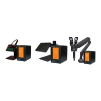
For cable management, tubes and cables can be routed
through a removable guide as shown in Figure 14.2.
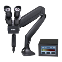
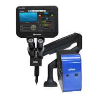
PJ Scope Set Up
MICROSCOPE SETUP
• Refer to the setup instructions that shipped
with the PJ Scope.
• Plug the included Shutter Cable into the RJ45
port on the microscope (the bottom of the
microscope head). See Figure 14.3.
• Plug the other end of the Shutter Cable into the
Shutter port on the front of the welder.
Note: Connecting non-Sunstone products to the RJ45
port on the Zapp Plus may damage the welder and/or
the other devices.
Figure 14.2. Tubing and other cables can be routed up
and through the removable cable guide portion of the
arm.
Figure 14.4. PJ Scope.