14
NOTE: DIAGRAMS & ILLUSTRATIONS ARE NOT TO SCALE.
Installation and Operation Instructions
900300-00, 02/2015
Innovative Hearth Products
Superior
TM
DRT35 See Through and Peninsula Direct Vent Gas Fireplace
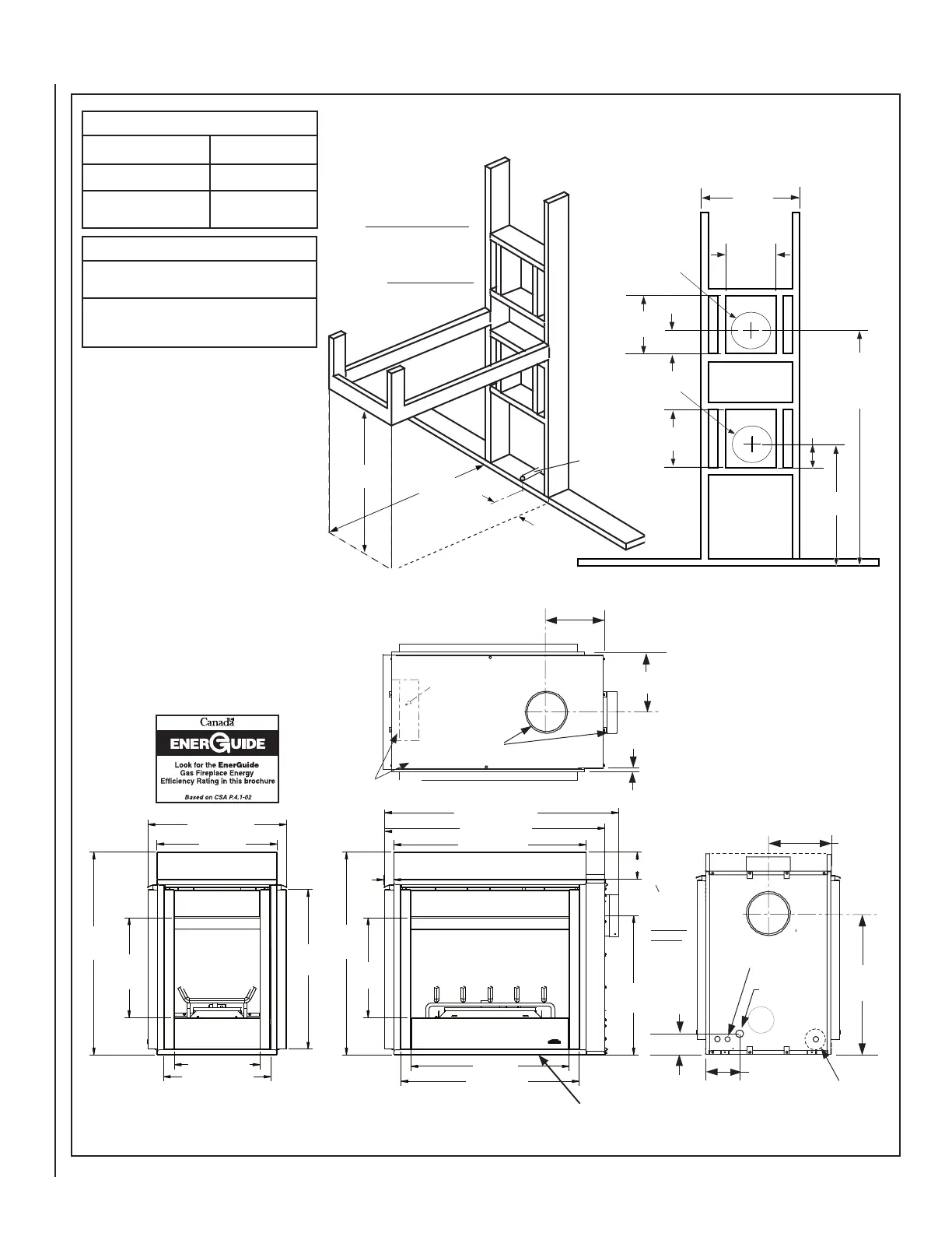
SPECIFICATIONS
Natural Gas BTU Input 30,000
Propane Gas BTU Input 28,000
Co-axial DV Vent Size
4-1/2" Inner /
7-1/2" Outer
NOTES
All specifications, ratings and dimensions are
subject to change without notice.
Appliance has a factory-installed vent seal cap
(see Figures 16 & 17 on Page 16) in each flue
outlet.
5-5/8
(143)
***38-3/4
(984)
37-3/16
(945)
(527)
10-1/2
(267)
12-1/8
(308)
5-1/8
(130)
12-1/8
(308)
25-1/2
(648)
5-1/8
(130)
Vent Center - Top Vent
with one 90 degree
elbow
Vent Center - Side Vent
with no elbows
Secure Vent
42-3/4 (1086)
Secure Flex
43-1/2 (1105)
**This dimension
based on 5/8" drywall.
For 1/2" drywall use
21" (533 mm). The
finished dimension
should be 22" (558
mm)
• Inches (millimeters)
•
Minimum Framing Stud Size is 2 x 4
• See
side views of fireplace below
for
gas line inlet location options.
Fireplace Framing Specifications
Center of gas line
is 3-1/8 inches
(79 mm) up from
floor.
Notes:
***This dimension does
not include the addition
of drywall to the inside of
framing or clearance for
the Side Vent Seal Cap.
Adjust accordingly for your
installation.
See also, Side Vent Seal Cap
note below.
Figure 14
Vertical Venting Through the Ceiling:
Frame ceiling opening - Use a plumb line
from the ceiling above the appliance to
locate center of the vertical run. Cut and/or
frame an opening, 10-1/2" x 10-1/2" (267
mm x 267 mm) inside dimensions, about
this center mark (see Figure 20).
11 (279)
6-1/4
(159)
25-1/2
(648)
3-1/8 (79)
10-7/8 (264)
11 (279)
(16)
5/8
25-5/16 (643)
22 (559)
15-3/4 (400)
19-11/16 (500)
37-1/16
(941)
18-1/4
(465)
29-3/16
(741)
37-1/16
(941)
18-1/4
(464)
1-1/4
(44)
4-15/16
(125)
25-1/2
(648)
41-13/16 (1062)
40-1/4 (1022)
35-1/4 (895)
29 (737)
32-5/8 (829)
Left Side View
Front View
Junction Box Knock-Out
(2 places each side)
Control Compartment
Door
Gas
Inlet
Control Switch Wires
Knock-Out
Provide
additional
space for
Side Vent
Seal Cap if
installing
against
a solid
wall.
Framing Spacers
(top and both sides)
Vent Seal Cap
Optional
Blower
Top View