53
NOTE: DIAGRAMS & ILLUSTRATIONS ARE NOT TO SCALE.
Installation and Operation Instructions
900300-00, 02/2015
Innovative Hearth Products
Superior
TM
DRT35 See Through and Peninsula Direct Vent Gas Fireplace
Position The Groove At The Bottom Of
Log (A) Over The Grate And Slide It
Forward Against The Grate Here
READ WARNINGS ON Page 50 BEFORE PROCEEDING
1. Remove the front glass enclosure panel (see Glass Enclosure Panel
Removal Instructions, Page 47).
2. Remove the following from firebox; log set, bag of embers and bag
of vermiculite. Handle logs carefully to prevent breakage.
3. Ensure the Grate is properly installed in the firebox with the 4 legs
of the grate fitting into the 4 dimples on the firebox floor.
4. Install Vermiculite - Place some vermiculite on the firebox floor around
the grate (the entire bag of vermiculite will NOT be used). See Figure
13 on Page 13. DO NOT PLACE ANY VERMICULITE ON THE BURNER.
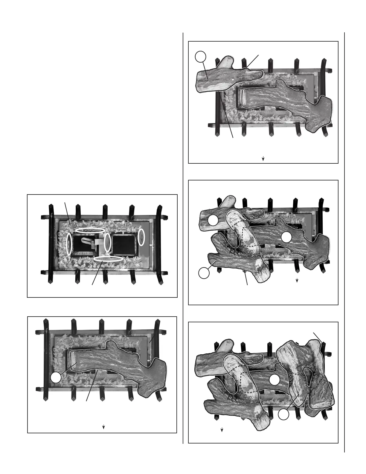
5. Placement of Glowing Embers -
Separate the Embers (rockwool) into pieces about the size of a quarter
(see Figure 77). Keep the pieces fluffed up, not matted. Distribute
these pieces over the surface of the burner, as shown in Figure 78.
Do not use more than is necessary. Ensure that the main burner ports
remain uncovered by the ember material.
Note: This appliance is provided with enough Glowing Embers for
several applications, do not use all that is in a new bag at one time. For
best glowing effect, replace the ember material annually. Replacement
Glowing Embers are available (order Catalog Number 88L53).
INSTALLATION STEPS:
B
A
(Valve Access Side)
(Valve Access Side)
Position Groove At The Bottom Of
Log (A) Over The Log Support Here
7. Place Log (B) as shown in Figure 8.
Position Log (B) Against The Back Of
The Grate Here
Position Groove at The Bottom Of Log (B) Over The
Grate Here And Slide It Against The Back Of The Grate
Figure 80
9. Place Log (D) as shown in Figure 10.
6. Place Log (A) on the grate as shown in Figure 7
Figure 81
8. Place Log (C) as shown in Figure 9.
C
(Valve Access Side)
Log (C) Lays Over Logs (A) and (B)
A
B
Position The Groove in The Back of Log (C)
Against The Grate
D
(Valve Access Side)
Position And Slide Log (D) Against The
Back Of
The Grate
A
Figure 82
Place Log (D) Over The
Flat Spot On Log (A)
Here
Figure 78
Place Embers on burner as shown.
DO NOT PLACE EMBERS OVER
GAS PORTS / AREAS CIRCLED
Figure 79
NOTE: DIAGRAMS & ILLUSTRATIONS ARE NOT TO SCALE.