46
NOTE: DIAGRAMS & ILLUSTRATIONS ARE NOT TO SCALE.
Installation and Operation Instructions
900300-00, 02/2015
Innovative Hearth Products
Superior
TM
DRT35 See Through and Peninsula Direct Vent Gas Fireplace
BTU Input
These fireplaces are designed as supplemental
heaters. Therefore, it is advisable to have an
alternate primary heat source when installed
in a dwelling.
Millivolt Models - The millivolt appliances are
manually controlled and feature a spark igniter
(piezo) that allows the appliance's pilot gas to
be lit without the use of matches or batteries.
This system provides continued service in the
event of a power outage.
Millivolt models come standard with a manually-
modulated gas valve; flame appearance and heat
output can be controlled at the gas valve. The BTU
Input for these appliances is shown in Table 12.
Electronic Models - Electronic models have a
fixed rate gas valve. Input of electronic models
is shown in Table 12.
Burn-in Period
During the first few fires of this appliance there
will be some odor due to the curing of the
paint and burning off of lubricants used in the
manufacturing process. Depending on your
use, the burn-in period may take a few hours
or a few days.
KEEP YOUR HOUSE WELL VENTILATED
DURING THE CURING PROCESS. THE ODOR
AND HAZE EMITTED DURING THE CURING
PROCESS CAN BE QUITE NOTICEABLE AND
MAY SET OFF A SMOKE DETECTOR.
If an optional blower is installed, Do Not turn
it on during the Burn-In period.
A white film may develop on the glass front
during the first few fires as part of the curing
process. The glass should be kept clean during
the first two weeks of use to prevent the film from
baking on (making it very difficult to remove).
See Cleaning Glass on Page 51.
Test gauge connections are provided on the
front of the millivolt and electronic gas control
valve (identified IN for the inlet and OUT for the
manifold side). The control valves have a 3/8"
(10mm) NPT thread inlet and outlet side of the
valve (refer to Figures 73 and 74).
Propane tanks are at pressures that will cause
damage to valve components. Verify that the
tanks have step down regulators to reduce the
pressure to safe levels.
These appliances must not be connected to a
chimney or flue serving a separate solid fuel
burning appliance.
Orifice Sizes - Sea Level to High Altitude
(All Models)
These appliances are tested and approved for
installation at elevations of 0-4500 feet (0-1372
meters) above sea level using the standard burner
orifice sizes (marked with an "*" in Table 15).
For elevations above 4500 feet, contact your
gas supplier or qualified service technician.
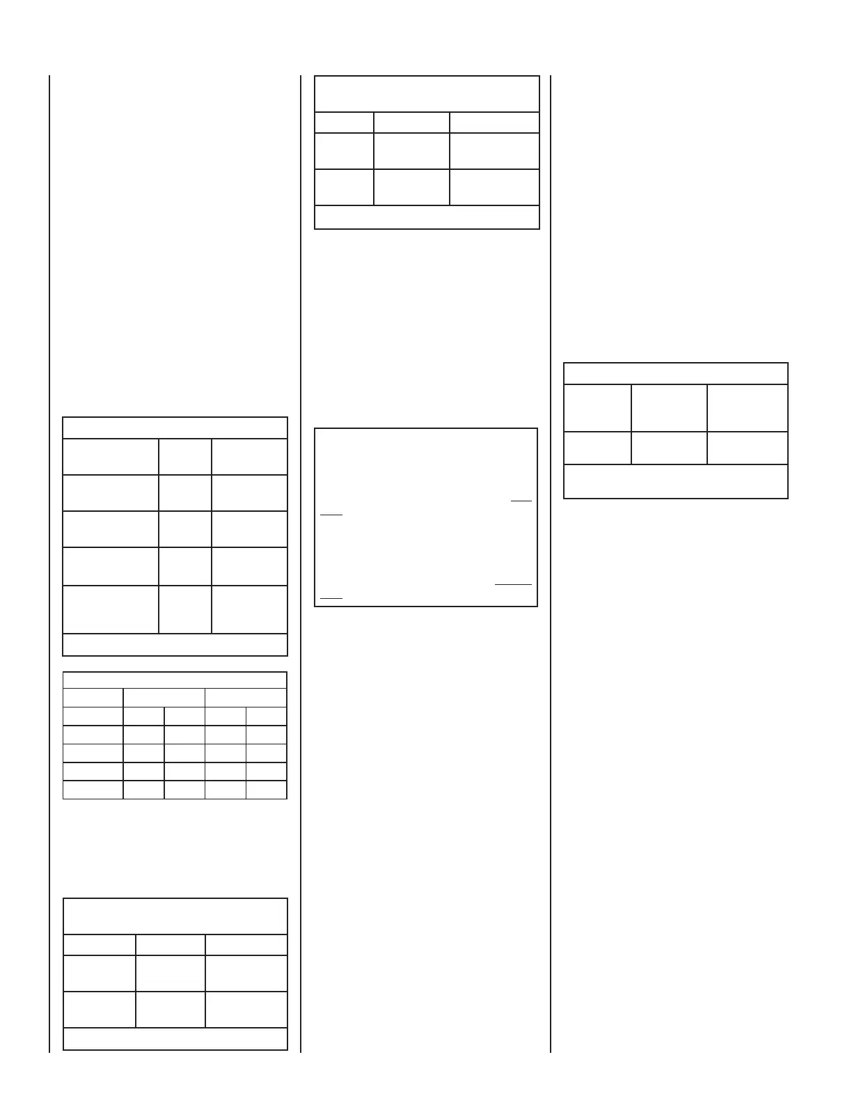
Manifold Gas Supply Pressure
(all models)
Fuel # Low High
Natural
Gas
(Lo) 2.2" WC
(0.55 kPa)
(Hi) 3.5" WC
(0.87 kPa)
Propane
(Lo) 6.3" WC
(1.57 kPa)
(Hi) 10.0" WC
(2.49 kPa)
Table 14
These appliances must be isolated from the
gas supply piping system (by closing their
individual manual shut-off valve) during any
pressure testing of the gas supply piping
system at test pressures equal to or less
than 1/2 psig (3.5 kPa).
These appliances and their individual shut-off
valves must be disconnected from the gas
supply piping system during any pressure
testing of that system at pressures greater
than 1/2 psig (3.5 kPa).
Inlet Gas Supply Pressure
(all models)
Fuel # Minimum Maximum
Natural Gas
4.5" WC
(1.12 kPa)
10.5" WC
(2.61 kPa)
Propane
11.0" WC
(2.74 kPa)
13.0" WC
(3.23 kPa)
Table 13
Gas Pressure - All Models
Tables 13 and 14 show the appliances' inlet and
manifold gas pressure requirements:
Deration - At higher elevations, the amount
of BTU fuel value delivered must be reduced
by either using gas that has been derated by
the gas company or by changing the burner
orifice to a smaller size as regulated by the
local authorities having jurisdiction and by the
(USA) National Fuel Gas Code NFPA 54/ANSI
Z223.1 - latest edition or, in Canada, the CAN/
CSA-B149.1 codes - latest edition.
Install the appliance according to the regulations
of the local authorities having jurisdiction and,
in the USA, the National Fuel Gas Code NFPA
54 / ANSI Z223.1 - latest edition or, in Canada,
the CAN/CSA-B149.1 - latest edition.
Flame breadth, height and width will dimenish
4% for every 1,000 feet of altitude.
Burner Orifice Sizes (all models)
Elevation
Feet (meters)
Natural
Gas
drill size (inches)
Propane
Gas
drill size (inches)
0-4500
(0-1372)
#37 (0.104")
*
24M10 •
1.55
mm
(0.061")
*
42M79 •
Table 15
* Standard size installed at factory
• Part /Cat. Number
Input (BTU) Gas Valves (all models)
Models Fuel
Type
Input Rate
(BTU / HR)
35" ST/PF DMN
(Millivolt)
Natural
30,000 high
23,000 low
35" ST/PF DMP
(Millivolt)
Propane
28,000 high
22,000 low
35" ST/PF DMN
(Electronic)
Natural 30,000
35" ST/PF
(Electronic)
(if field converted)
Propane 28,000
Table 12
Efficiencies %
Natural Gas Propane
Models AFUE P4 AFUE P4
STDMN-P
68.8 59.03 70.3 58.66
STDEN
74.8 54.73 n/a n/a
PFDMN-P
69.2 60.1 69.7 58.66
PFDEN
74.8 54.73 n/a n/a