MOUNTING
BOLT
SERVICING YOUR SUPERMAX
31
4. Align the V-belt pulleys with the pulley on the
motor and then tighten the set screws in the V-belt
pulleys. Spin the drums by hand to make sure the
pulleys are in proper alignment.
5. Check the alignment of the front drum to the
conveyor table. If they are not parallel, level the
front and then the rear drum (see pages 7 and 8)
before proceeding further.
6. Readjust the tension of the V-belt by sliding the
motor down and then tightening the pinch bolt in
the motor support casting. Make sure all pulleys are
aligned and all bolts tight before using the sander.
7. Reinstall the outer belt guard using the two
5/16" x 1/2" hex head bolts. Reinstall the lower
belt guard using the two 10-32 screws and the
middle, inner guard using two 10-32 screws.
REPLACING CONVEYOR BELTS
To replace the conveyor belt, the conveyor assem-
bly must be removed from the machine. Lower the
conveyor table to its lowest position with the
height adjustment handle. Remove the bottom
cover from control box, rotate shaft to access set
screws in shaft coupler. Important: Disconnect
power to sander. Loosen one set screw. Remove
the four 5/16" bolts holding the conveyor motor
control box base bracket (Fig. 45). Remove con-
veyor motor control box and place on dust cover.
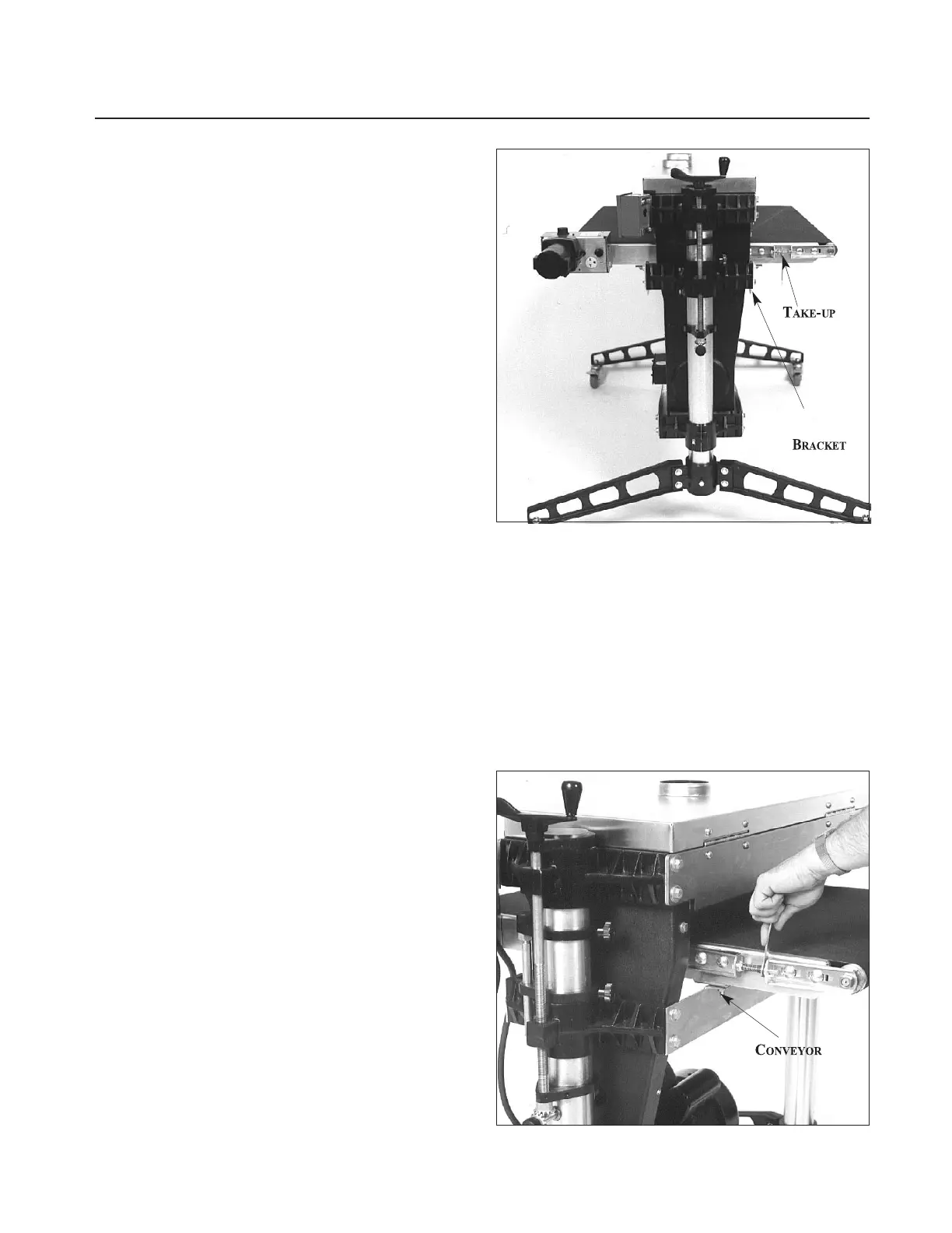
Loosen the conveyor take-up screws (Fig. 35 and
Fig. 36) to relieve belt tension and slide the driven
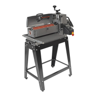
roller fully inward. Remove the four bolts that
attach the conveyor assembly to the table mount
brackets (see Fig. 36). Lift the conveyor and
remove it from the machine by sliding the convey-
or out toward the front of the machine. Avoid
tearing the belt on any edges underneath the con-
veyor bed during removal. Reverse the procedure
for re-installation.
Note: If the conveyor belt continually tracks to
one side of the machine, first try reversing the belt
on the conveyor bed. If this doesn’t remedy the
problem, place a level on the conveyor bed to
make sure the conveyor bed is not twisted. If it is
twisted, see page 7 for instructions on squaring up
the bed. If squaring up the bed does not remedy
the problem, proceed with the steps below:
Fig. 35. Conveyor belt replacement.
Step 1. Check the conveyor drive and driven roller
to make sure they are parallel to the surface of the
conveyor bed. To do this, first center the conveyor
belt on the bed. Then lay a straight-edge on the
exposed edge of the conveyor table on the left (out-
board) side, extending it over the drive roller, then
driven roller. Note the distance between the drive
roller then driven roller and the straight-edge.
Fig. 36. Tensioning and tracking conveyor belt.
SCREW
TABLE
MOUNT